Operators Manual Model PT2000/H Series Gas Monitor Rev 2. January 2014
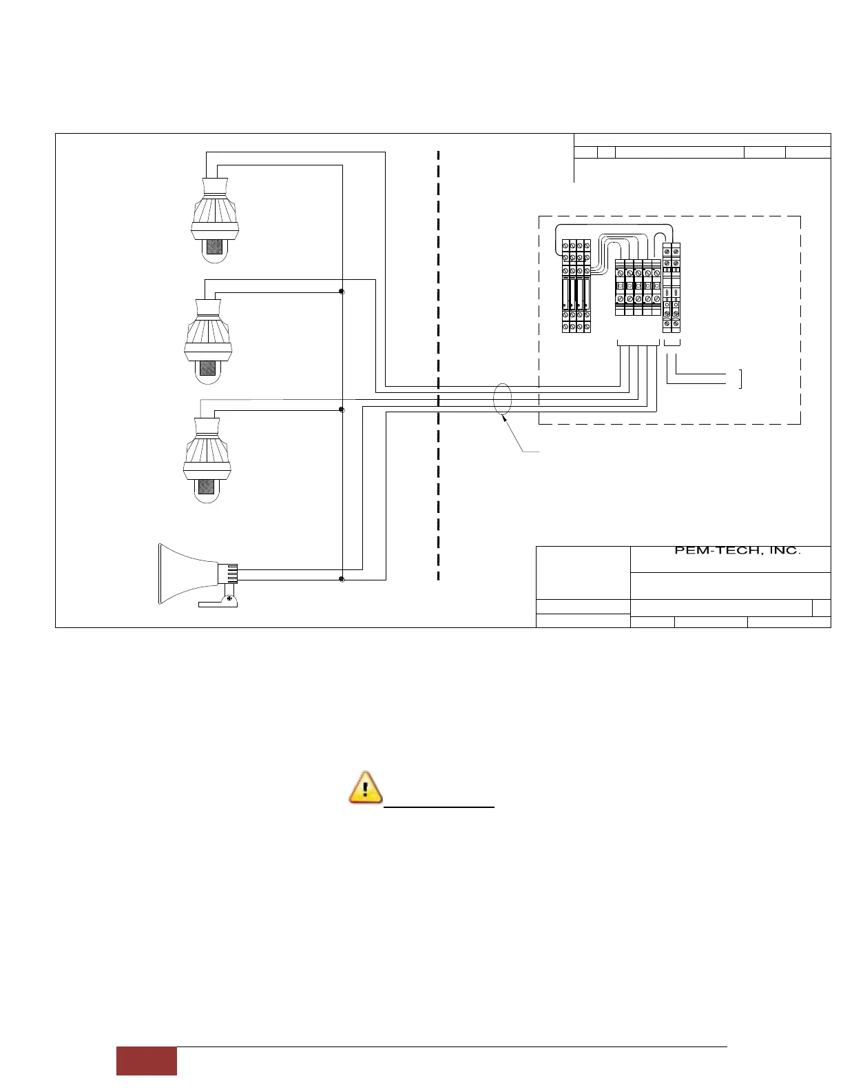
To connect a 4 Device Alarm Station 5 core cable is used. One core each for the +V
terminal of the device and 1 common for Return.
WARNING
Do not use the DC power from the onboard AC/DC power supply as a power source
for the DC powered Alarm devices. External DC power source must be used for these
devices.
Visual Alarm 1
Visual Alarm 2
Visual Alarm 3
Audible Alarm 4
Alarm Wiring Diagram
(A1)
(A2)
(A3)
(A4)
+V
RETURN
RETURN
RETURN
RETURN
+V
+V
+V
B2013139
1
1 OF 1
6A RELAY
6A RELAY
6A RELAY
6A RELAY
+v
Ret
A2
A1
14
11
12
A2
A1
14
11
12
A2
A1
14
11
12
A2
A1
14
11
12
(+V) AL-1
Return
(+V) AL-2
(+V) AL-3
(+V) AL-4
Pwr Source
A/V Alarms
RLY-1
RLY-2
RLY-3
RLY-4
BUSS
BUSS
BUSS
+v
Ret
Pwr Source
for Alarm Devices
PT2000H Gas Controller
5 Core Cable
Relay Terminal Block on
PT2000H Controller
07/19/2013
RM
(AC / DC)
Figure 3.Wiring Diagram. Audio/Visual Alarm Connection