EasyManua.ls Logo

PEMTECH PT2000/H Series - 3.4 Connection & Wiring Diagram for Audio; Visual Alarms

Default Icon
56 pages
Print Icon
To Next Page IconTo Next Page
To Previous Page IconTo Previous Page
Loading...
12
Operators Manual Model PT2000/H Series Gas Monitor Rev 2. January 2014
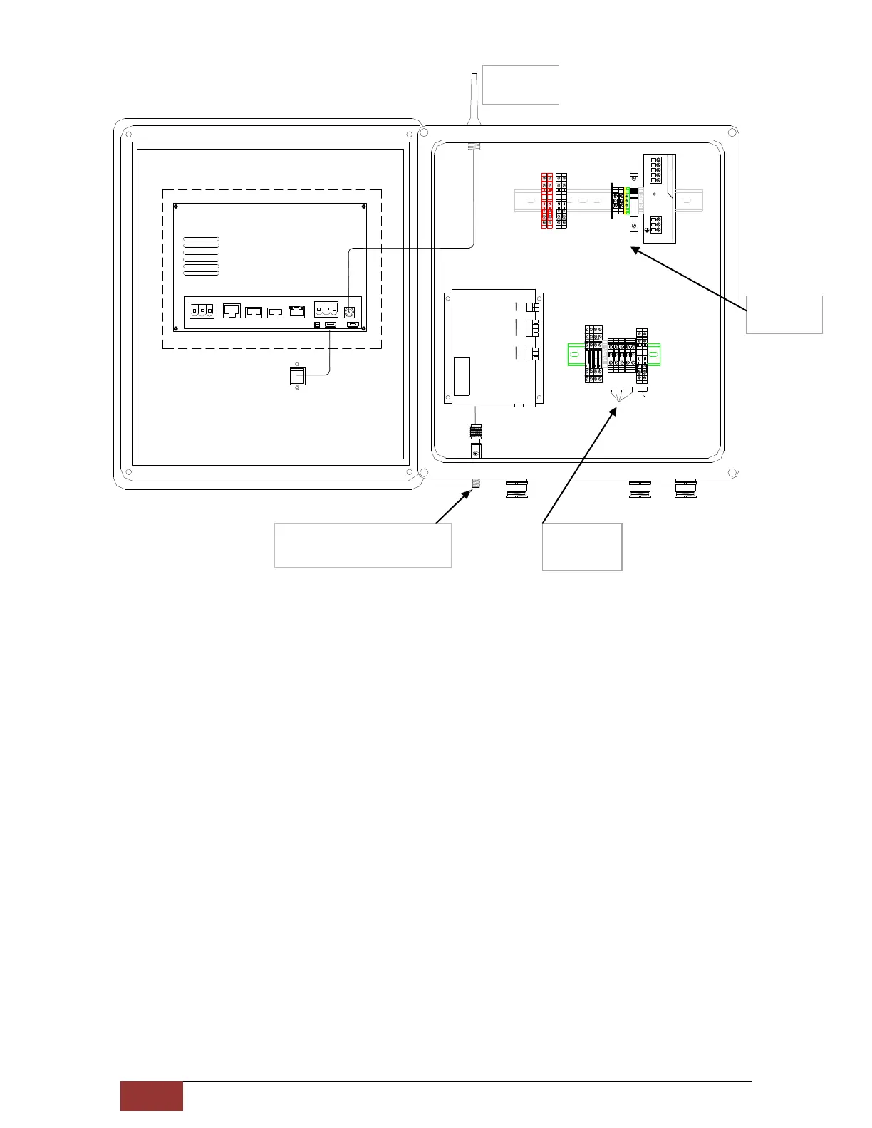
3.4 Connection & Wiring Diagram for Audio / Visual Alarms
PT2000 Controller has 4 each programmable alarm relay contacts. These relays are
pre-wired to activate the audio and visual alarm devices. Refer to figure 3 for wiring
diagram. Each alarm relay is rated 6 Amps (AC/DC)
Note: Use an in-line fuse at the Alarm Power Source Connection terminals to avoid
damage to the Relays and controller.
Figure 2. PT2000H Controller. Inside View
Main AC
Power IN
Audio/Visual
Alarm
Connections
Coax Cable connector for
External Omni Antenna














































BREAKERBREAKER
































  








Antenna for
Cell Modem

Related product manuals