Operators Manual Model PT2000/H Series Gas Monitor Rev 2. January 2014
8.0 Normal Operation
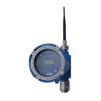
Ultra1000 series Wireless Detector ( toxic / Combustible) is used for air quality
monitoring. The unit detects the target vapors or fumes in air and sends the signal to
the control monitor over wireless data network. In a normal operation mode and zero
(no gas) state the sensor transmits the data every 90 seconds to the controller.
However, during alarm or in the presence of the gas in the air the data is transmitted
every 2 seconds. This transmission rate of data has been selected to maximize the
battery life.
8.1 Programming Sensor Address & Zone/Network ID
The first step after unit power up is to assign the sensor Address (Unit ID) and Network
/ Zone ID. The sensor address and zone id needs to be programmed only once. The
data is retained in a non-volatile memory and is not lost when the detector is powered
down. Address and ID are recalled from the memory when the unit is powered up
again.
Note: The addresses to each sensor are assigned at the factory when a complete
system is shipped. However, when a single replacement sensor is purchased then
user must assign the address to the sensor.
In order for the detector to communicate with PT2000 Series Control Monitor each
sensor must be assigned a unique address. The sensor uses this address to identify
itself when transmitting data to the monitor over wireless network. Network ID must
also be set. Network ID for all detectors must be the same as the Controllers Network
ID. Network ID is used to avoid any crosstalk between devices if multiple Systems are
used within the communication range of each other.
Follow the step by step instructions to assign a unique address to the
sensor.
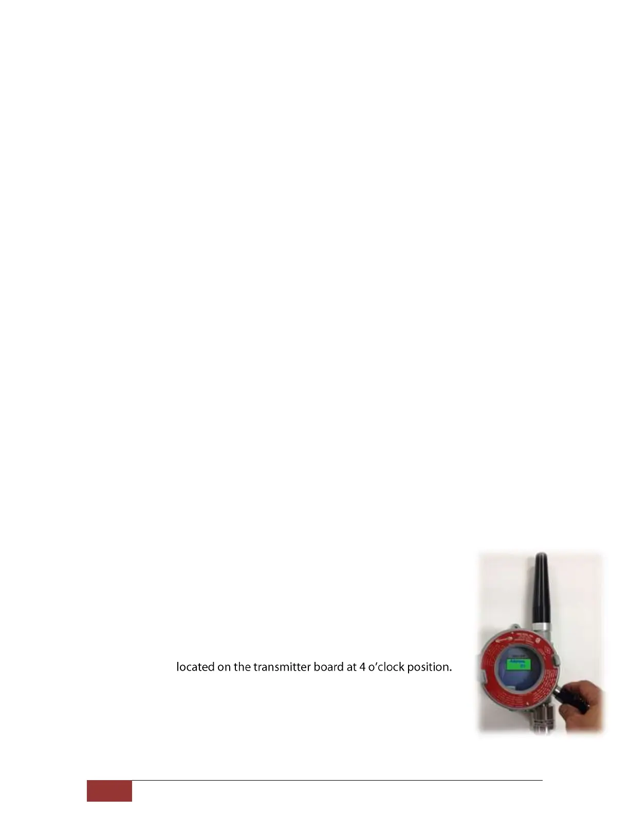
1. Using the magnet supplied with the unit, activate the internal
magnetic switch. Refer to figure 10 for the position of the address
configuration switch.
The switch is
2. The sensor enters into address programming mode and the current
address is displayed for few seconds.
Figure 10. Setting Unit Address