EasyManua.ls Logo

PEMTECH PT2000/H Series - Page 20

Default Icon
56 pages
Print Icon
To Next Page IconTo Next Page
To Previous Page IconTo Previous Page
Loading...
20
Operators Manual Model PT2000/H Series Gas Monitor Rev 2. January 2014
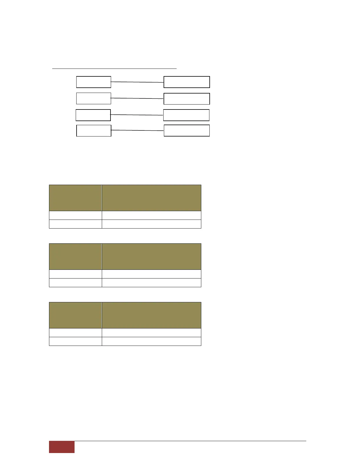
Consider the following A/V alarm logic:
Relay Connection to Audio/Visual Devices
If the alarm station is wired to the controller as shown in figure 3 wiring diagram and
as per logic diagram above, then the alarm devices will activate as indicated in the
following table:
Note that Horn (Relay # 4) is common Audible Alarm for all 3 gas sensor type.
H2S Detector
Readings
A/V Device Activated
10 ppm
Low Alarm Blue Strobe
15 ppm
High Alarm Horn
LEL Detector
Readings
A/V Device Activated
20 %
Low Alarm Red Strobe
40 %
High Alarm Horn
SO2 Detector
Readings
A/V Device Activated
10 ppm
Low Alarm Amber Strobe
20 ppm
High Alarm Horn
Relay # 1
Blue Strobe
Relay # 2
Red Strobe
Relay # 4
Horn / Siren
Relay # 3
Amber Strobe

Related product manuals