Operators Manual Model PT2000/H Series Gas Monitor Rev 2. January 2014
9.0 Sensor Calibration
Refer to Table at the end of this section for the recommended calibration gas for the
target sensor.
Following items are needed for the sensor calibration:
Calibration adapter with tubing
Magnet tool to activate the magnetic sensor on the transmitter board assembly.
Calibration gas bottle with flow regulator. The flow of the calibration gas should
be approximately 1.5 LPM (liters per minute)
See Figure 12
The sensor can be auto calibrated without removing the enclosure cover and
declassifying the zone. A magnet tool is used to activate the internal switch to initiate
the calibration.
Follow the steps below to calibrate the sensor.
1. Make sure the detector and ambient air is clear of gas
vapors.
2. Remove the rain / splash guard if attached.
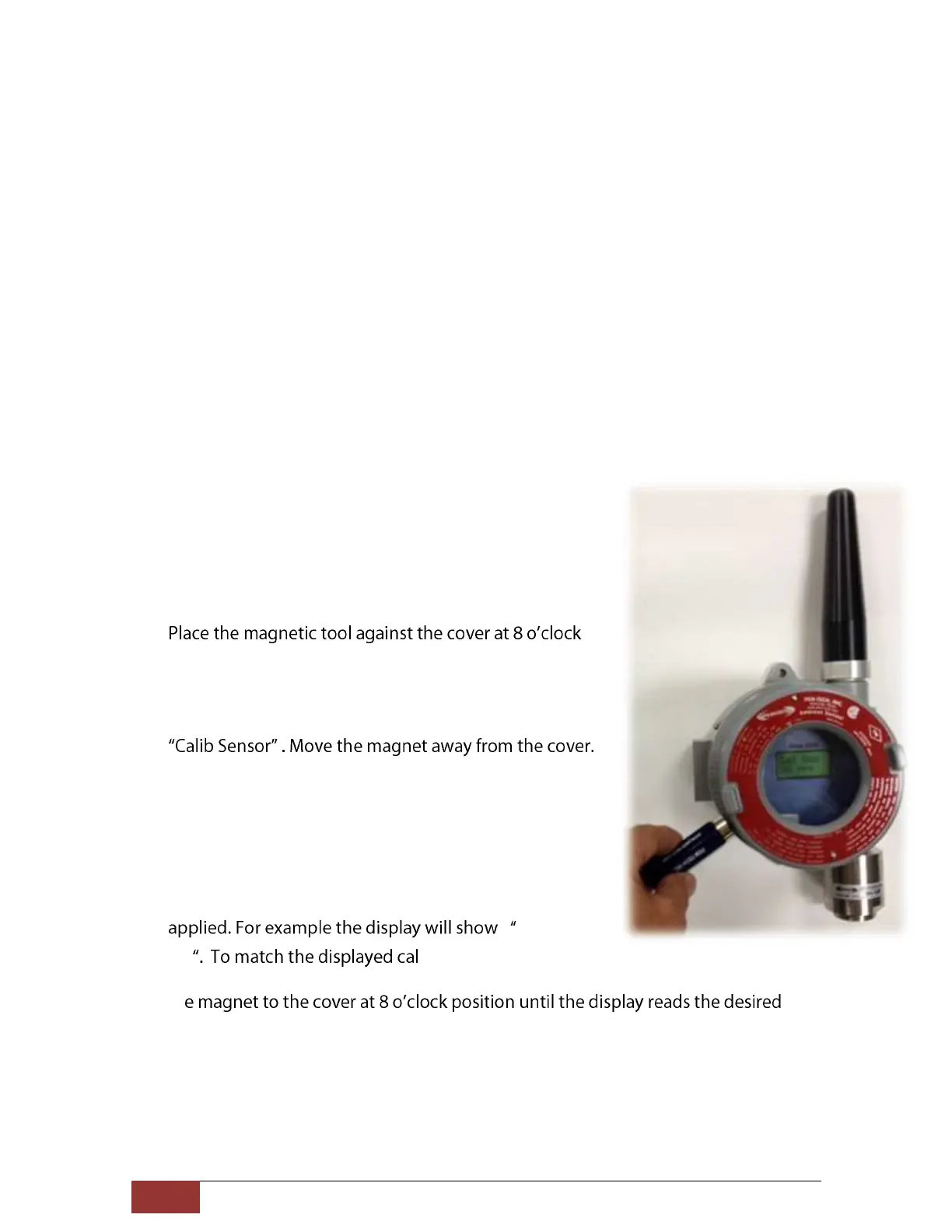
3.
position to activate the magnetic switch as shown in
figure 11.
4. Place and hold the magnet until display indicates the
5. While the Calib Sensor message is being displayed the
sensor is making its initial adjustments. It may take 5 to
10 seconds. (Note: Do not apply calibration gas yet)
6. Once the initial adjustments are made the sensor will
display the concentration of the calibration gas to be
Cal Gas
50 -gas reading to the
calibration gas bottle being used simply place and hold
th
cal-gas value. Typically the calibration is performed at mid scale. For example, the
H2S sensor with the detection range of 100 ppm the typical calibration gas should
be 50 ppm. The selected calibration gas value will be stored in the non-volatile
memory and remains unchanged until modified.
Figure 11.Sensor Calibration Mode.