icons and the associated analog output setup value
relationships.
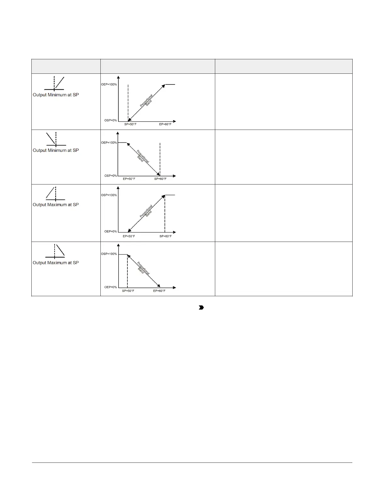
Table 6: Analog Output control ramp icons
Control ramp displayed on
LCD
Control action Set the Analog Output value relationships for the
desired control action and control ramp
SP < EP
OSP < OEP
SP > EP
OSP < OEP
SP > EP
OSP > OEP
SP < EP
OSP > OEP
Setting Up the Integration Constant, Update Rate,
and Output Deadband
The System 450 Integration Constant (I-C), the Update
Output Signal Rate (UP-R), and the Output Signal Strength
Deadband (bNd) are powerful tools for controlling the
analog outputs and your application’s process loops.
Depending on your control system application, setting
up the I-C, UP-R, or bNd values to values other than
the factory-default values can significantly change the
behavior of an analog output. Refer to the System 450
Series Modular Control Systems with Communications
Control Modules Technical Bulletin (LIT-12011826) for more
information.
Important: If you set the I-C, UP-R, or bNd values
to values other than the default value, you should
operate and observe the affected analog outputs
and process loops through the entire range of
control. Failure to observe and adjust an analog
output set up to use the I-C, UP-R, or bNd features
can result in unexpected behavior and out of range
conditions in the affected process loops.
This section provides information, procedures, guidelines,
and screen examples for setting up analog outputs on
System 450 control modules with communications. See
Figure 62 for example menu flow of the Analog Output 3
set up in this section.
1. In the Analog Output Setup Start screen, press
Next to go to the output’s Sensor Selection screen.
The output numbers and the output type (relay
or analog) are determined by the module types
and configuration of your control system’s module
assembly and are automatically assigned when you
connect power to the module assembly. (See Setting
up the Control System in the UI.)
System 450 Series Control Module with Ethernet Communications Installation Guide 15
 Loading...

