SCREENLOGIC
®
INTERFACE Wireless Connection Kit Installation Guide
1
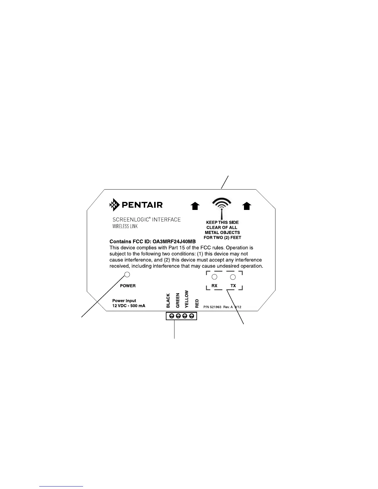
Antenna
location
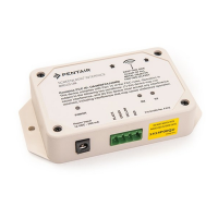
RX: This LED is
on when a signal
is being received
from the wireless
transceiver in the
outdoor clam
shell.
TX: This LED is
on when a signal
is being
transmitted to the
wireless
transceiver in the
outdoor clam
shell.
RS-485 Connector
(to Protocol Adapter)
Power LED
ScreenLogic Interface
Summary installation steps
The ScreenLogic
®
Interface connection diagram on page 2 shows the
transceiver locations and connections. To install the ScreenLogic Interface
Wireless Connection kit:
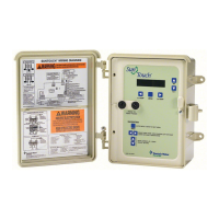
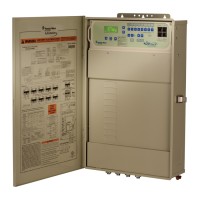
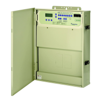
• Mount the transceiver antenna near the IntelliTouch
®
or
EasyTouch
®
Control System Load Center and connect the
transceiver to the COM port connector located in the IntelliTouch
®
or EasyTouch
®
Control System Load Center.
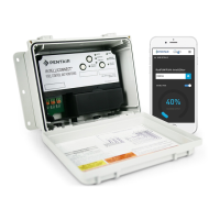
• Use the supplied 12 inch cable to connect the ScreenLogic
Interface indoor wireless transceiver to the ScreenLogic Interface
Protocol adapter. Plug the transceiver AC power adapter into an
AC wall-outlet and into the transceiver unit to power up the unit.