SCREENLOGIC
®
INTERFACE Wireless Connection Kit Installation Guide
3
Step 1:
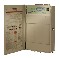
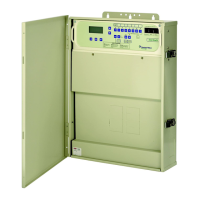
Mount the Outdoor Wireless Transceiver and Connect to the
IntelliTouch
®
or EasyTouch
®
Control System Load Center
The following describes how to mount the transceiver the IntelliTouch
®
or
EasyTouch
®
Control System Load Center and connect the four-wire cable
to the COM port connector located in the IntelliTouch or EasyTouch
Control System Load Center:
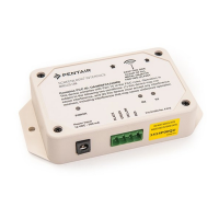
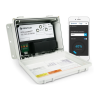
Mount the Transceiver Module
The Transceiver is a two-way radio device with an attached antenna that
communicates to and from the IntelliTouch or EasyTouch Control System.
Mount the transceiver at a convenient location (on a flat vertical surface) near
the load center, at a minimum of 5 ft. above ground level to optimize the
transmit and receive operating range.
1. Remove the two retaining screws located on the underside of the
transceiver case. Slide the case off the back plate.
2. Position the back plate against the mounting surface so that the
transceiver is oriented in an upright position (with the antenna
pointing upwards). Use a pencil to mark the four mounting points.
Drill four 3/16 in. diameter holes into the mounting surface and
insert the four plastic anchors (provided in the kit).
Note: To avoid signal interference, mount the transceiver a
minimum of 10 feet away from the load center, any metal
surface/structure, or air blower located in the immediate area
of the equipment pad.
3. Position the back plate over the mounting points and secure it with
the four mounting screws (provided in the kit).
4. Carefully position the transceiver circuit board into the mounted
back plate. Route the connection wire down through the lower exit
hole (left side) at the bottom of the back plate. Carefully pull the
wire out the lower hole and position the circuit board in the back
plate.
5. Position the transceiver circuit board to the left side of the back
plate, and slide the case over the circuit board and antenna into
the back plate. Secure the circuit board in the case using the two
retaining screws.
6. Proceed to “Connect the Transceiver connection cable to the
COM Port on Control Systems Circuit Board” on the next page.