SCREENLOGIC
®
INTERFACE Wireless Connection Kit Installation Guide
5. Route the four conductor transceiver connection cable into the
lower plastic grommet, up through the low voltage raceway to the
circuit board.
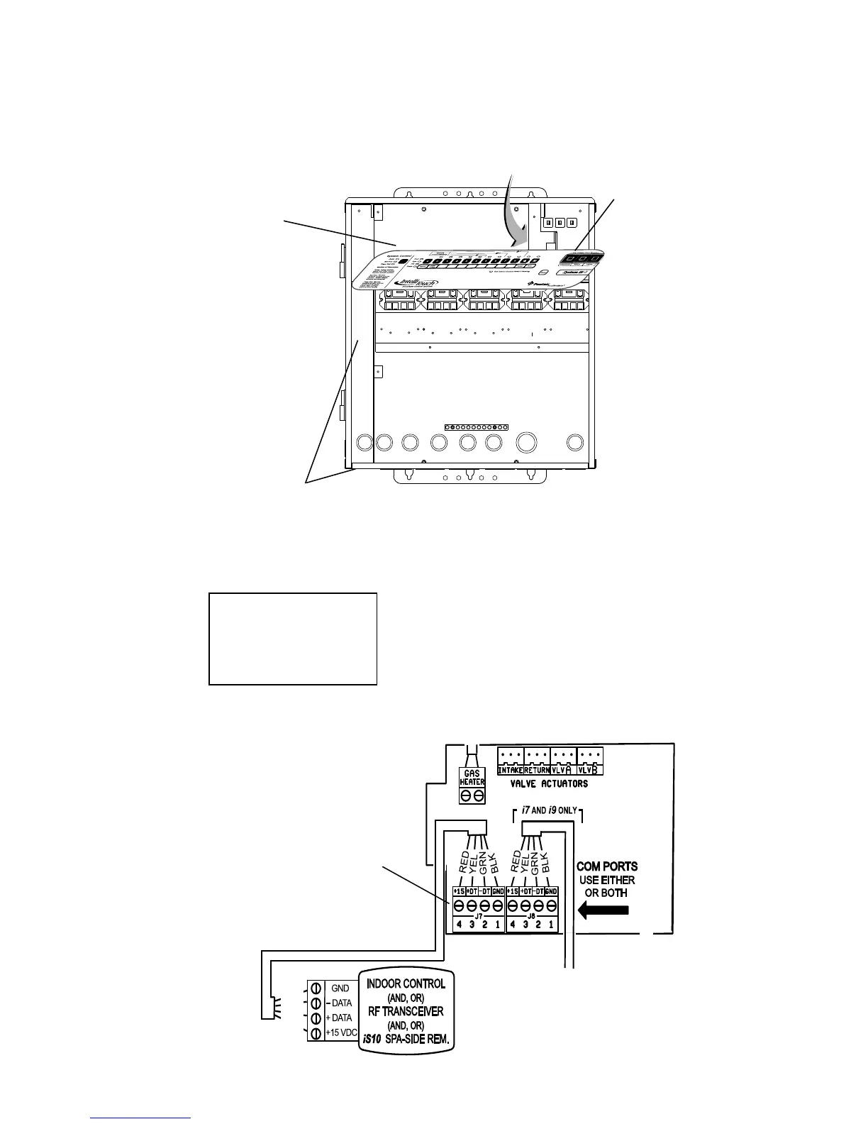
6. Insert the four wires into the screw terminals of the COM PORT
plug located on the circuit board as shown on page 6. Using a
small flat-blade screwdriver, secure the wires with the screws.
Make sure to match the color coding of the four wires:
Pin 4 - Red = +15
Pin 3 - Yellow = +DT
Pin 2 - Green = -DT
Pin 1 - Black = GND
6
BLK
GRN
YEL
RED
Raceway
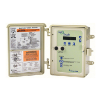
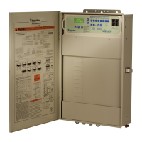
IntelliTouch
®
or
EasyTouch
®
Control
System COM Ports
(J7/J8) screw terminal
connector
Note: Multiple wires may be
inserted into a single screw
terminal but increases the
chances of a poor or intermittent
connection.
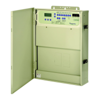
Control panel
Circuit board