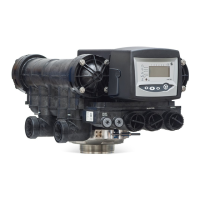
Installer manual Siata V132 - SFE - Installation
Ref. MKT-IM-003 / B - 19.04.2017 43 / 88
5.9. Drain line connection
Note
Standard commercial practices are expressed here. Local codes may require changes to
the following suggestions. Check with local authorities before installing a system.
The unit should be above and not more than 6.1 m (20 ft) from the drain. Use a 22 mm hose tube.
The drain line may be elevated up to 1.8 m (6 ft) providing the run does not exceed 4.6 m (15 ft) and
water pressure at the conditioner is not less than 2.76 bar (40 psi). Elevation can increase by 61 cm
(2 ft) for each additional 0.69 bar (10 psi) of water pressure at the drain connector.
Where the drain line is elevated but empties into a drain below the level of the controller valve, form
a 18 cm (7") loop at the far end of the line so that the bottom of the loop is level with the drain line
connection. This will provide an adequate siphon trap.
Where the drain empties into an overhead sewer line, a sink-type trap must be used.
Secure the end of the drain line to prevent it from moving.
Note
Waste connections or the drain outlet shall be designed and constructed to provide
connection to the sanitary waste system through an air-gap of 2 pipe diameters or 25.4 mm
(1"), whichever is larger.
Caution
Never insert the drain line directly into a drain, sewer line or trap. Always allow an air gap
between the drain line and the wastewater to prevent the possibility of sewage being back-
siphoned into the conditioner.
A
A
 Loading...