18
English
Secon 5
Installaon
This secon describes how to install the SC-75 Salt Chlorinator into the pool plumbing system. Before installing, review the
SC-75 kit contents and required tools.
Note: For Power Center installaon instrucons, see the “SC-75 Power Center Installaon Guide”
Note: Salt is not provided. For details about the type of salt to use, see “What Type of Salt to Use” .
Required Tools
- Tape measure
- Phillips and athead screwdriver
- Pliers and Hacksaw
- An NSF® approved all-purpose PVC/CPVC/ABS cleaner primer
- An NSF® approved all-purpose PVC/CPVC/ABS cement
When using electrical products, basic precauons should always be followed, including the following:
DANGER: RISK OF ELECTRIC SHOCK, WHICH CAN RESULT IN SERIOUS INJURY OR DEATH.
Before aempng installaon of service, ensure that all power to the circuit supplying power to the system is
disconnected/turned o at the circuit breaker. It is recommended that the SC-75 Power Center be connected
to a circuit protected by a ground fault circuit-interrupter (GFCI).
• Grounding (earth bonding) is required. The unit should be installed by a qualied service person and grounded.
• Install to allow access to cell buons and power center.
• Read Safety Precauons and Important Instrucons. Before aempng any electrical wiring, be sure to read and follow
Safety Instrucons. Wiring should only be performed by a qualied professional.
• Install the SC-75 unit a minimum 1 meter away from the heater outlet.
• Pipe couplings: Schedule 80, maximum pressure 5 Bar (75 psi) at 21° C - PVC pipe 50mm
• Operate unit with minimum ow of 6m³/h. For high ow applicaons, use a bypass loop for best ow sensing.
• Provide at least 300mm-450mm of straight pipe in front of the cell inlet.
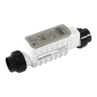
Installing the SC-75 Cell Assembly
Install the SC-75 cell assembly no closer than 900mm away from the heater outlet, if used.
Note: For best ow sensing, provide at least 300mm – 450mm of straight pipe in front of the cell inlet.
Note: Pipe couplings: Schedule 80, maximum pressure 5 Bar (75 psi) at 21° C
To install the SC-75 cell:
1. Using PVC glue, mount the PVC couplings to the plumbing pipe. Allow the glue to dry.
2. Mount the cell to allow access to the control panel. Install the cell onto the couplings.
3. Ensure the O-rings are seated properly.
4. Switch on the pump and visually inspect for leaks around the couplings.
Connecng the Cell Power Cable to the Power Center
Aer the cell installaon is completed, connect the power cable to the Power Center:
Switch OFF main system power to the Power Center before making any connecons
1. Be sure that AC power is switched OFF before connecng the power cord to the Power Center.
2. Align the four (2) pins of the cell power cord connector with the socket on the boom of the Power Center and insert
the connector. Turn the round socket nut unl it locks the connector in place.
Connector Socket Nut
To cell assembly
 Loading...