5
English
• Flow Sensor: A ow sensor assures that there will always be adequate water ow through the SC-75. If the SC-75 is not
properly plumbed and/or does not receive adequate water ow, no chlorine will be produced.
• Temperature Sensor: To protect the SC-75 from operaon and potenal damage when the temperature of the pool water
falls below 11° C, ±1.67° C, the temperature sensor switches the cell o, illuminates the COLD WATER light and no chlorine
will be produced.
• Salt Sensor: Two (2) salt sensor probes in the SC-75 are acvated each me the SC-75 is switched on and again during
every 12 hours of connuous running. At each of those mes, the salt level LED indicator lights ash in a scrolling sequence
for two (2) minutes to indicate that the SC-75 is in analysis mode. Aer two (2) minutes, the LED indicators lights will signal
one (1) of three (4) salinity ranges. For more informaon, see “Salt Level Status LEDs”.
Note: The salt sensor reading is within +/- 500 ppm accuracy.
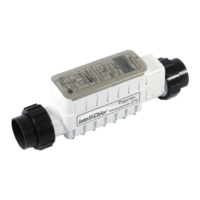
SC-75 Power Center
The power supply is connected with the pool circulaon pump electrical source so that the SC-75 only operates when the
pool pump is on. The Power Center should be mounted vercally on the wall up to three (3) meter away from the cell. The
Power Center contains the transformer, fuse, and connector to the cell. A fuse holder is mounted on the boom of the Power
Center for addional protecon. There are no other controls or lights on the Power Center. For informaon about installing
and proper use of the Power Center, see the “SC-75 Power Center Installaon Guide” .
The SC-75 Power
Center does NOT
control the pump. The SC-75 Salt
Chlorinator only produces chlorine
when the pool pump is on.
Before plugging or
unplugging the SC-
75 Salt Chlorinator to the Power
Center, rst switch o the AC
power to the Power Center.
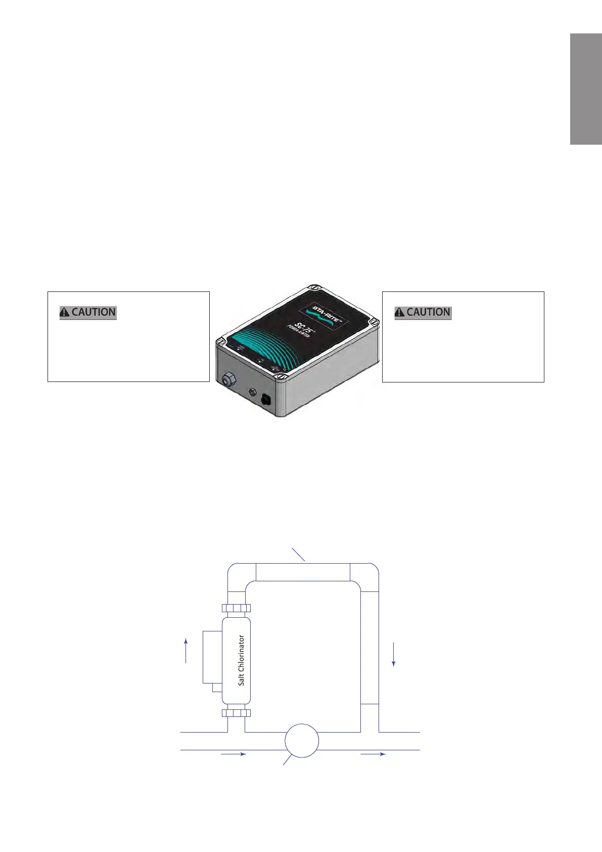
Loop Plumbing Diagram
The SC-75 Salt Chlorinator is designed to operate with water ow rates from 5.7 m³/h to not exceed 24 m³/h. For ow rates
over 18 m³/h minute you must use a bypass loop (as shown below) for best chlorine producon. Installaons with ow
rates over 18m³/h include those that have in-oor cleaning systems or booster pumps. These systems MUST use a bypass
loop with the SC-75 with a ow control valve that assures that the ow through the SC-75 is maintained within its designed
operang water ow rates.
Bypass Loop
FLOW
OUT
FLOW
IN
VALVE
FLOW IN
FLOW OUT
Flow Control Valve
“UPWARD FLOW”
NOT TO SCALE
SC-75
 Loading...