27640 -16/34-
3
33
3-
--
-4. Remove 2 lead wires and resistance
4. Remove 2 lead wires and resistance4. Remove 2 lead wires and resistance
4. Remove 2 lead wires and resistance which were installed for testing purpose
which were installed for testing purpose which were installed for testing purpose
which were installed for testing purpose
and remove solder on Main SW land.
and remove solder on Main SW land.and remove solder on Main SW land.
and remove solder on Main SW land.
3
33
3-
--
-5. 0
5. 05. 0
5. 0-
--
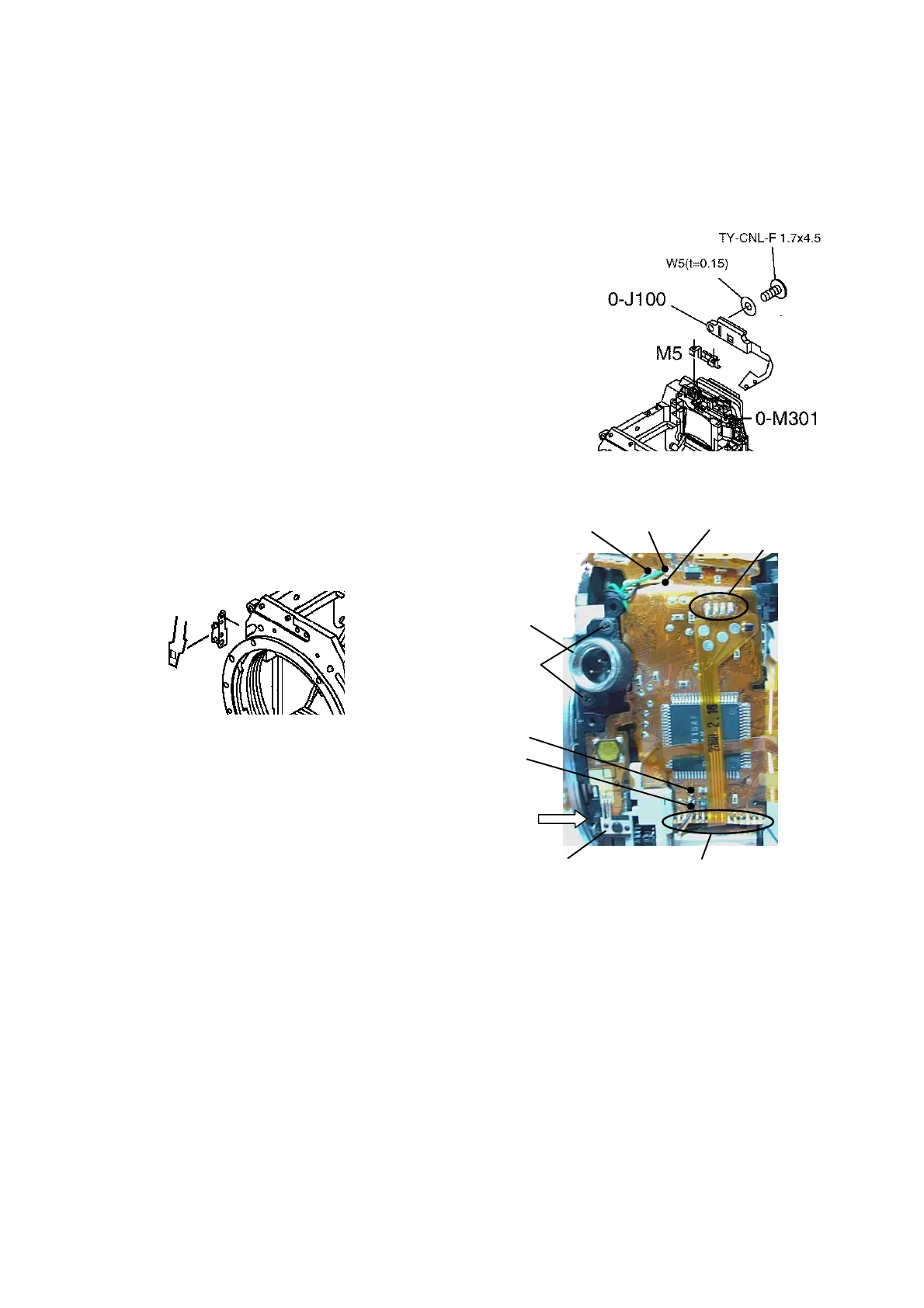
-J100(Light receiving sensor)
J100(Light receiving sensor)J100(Light receiving sensor)
J100(Light receiving sensor)
1) Pull diopter adj. part of 0-M301 towards the left hand side.
2
22
2)
))
)
Install M5 into 0-J100・・・W5(0.15), 1 screw.(for Temporary).
3
33
3-
--
-6.
6. 6.
6. Install 0
Install 0Install 0
Install 0-
--
-T100. (0
T100. (0T100. (0
T100. (0-
--
-A101 left hand side)
A101 left hand side)A101 left hand side)
A101 left hand side)
--
----
-- 0
0 0
0-
--
-A101 Left hand side
A101 Left hand side A101 Left hand side
A101 Left hand side --
----
--
1) I401(2 screws)・AF mode SW land.
(Apply G151 onto the land.)
2) 0-I331(Apply G151 into the rectangular hole
at the side.)
3) Solder 0-M100 lands(14 lands)・0-S300 Flex.(4 lands).
4) 5 lead wires(Orange・Black from 0-J201,Green・Yellow
・Black from K101)
--
----
-- 0
0 0
0-
--
-A101 Right hand side
A101 Right hand side A101 Right hand side
A101 Right hand side --
----
--
5) Install mount LED portion.
Black Green Yellow (K101)
0-S300(4)
I401
TY-CNL-D
1.7x4.5
Black
Orange
(0-J201)
TY-CNL-G
1.7x2.5
0-I331 0-M100(14)

 Loading...