27640 -20/34-
4
44
4-
--
-13. 0
13. 013. 0
13. 0-
--
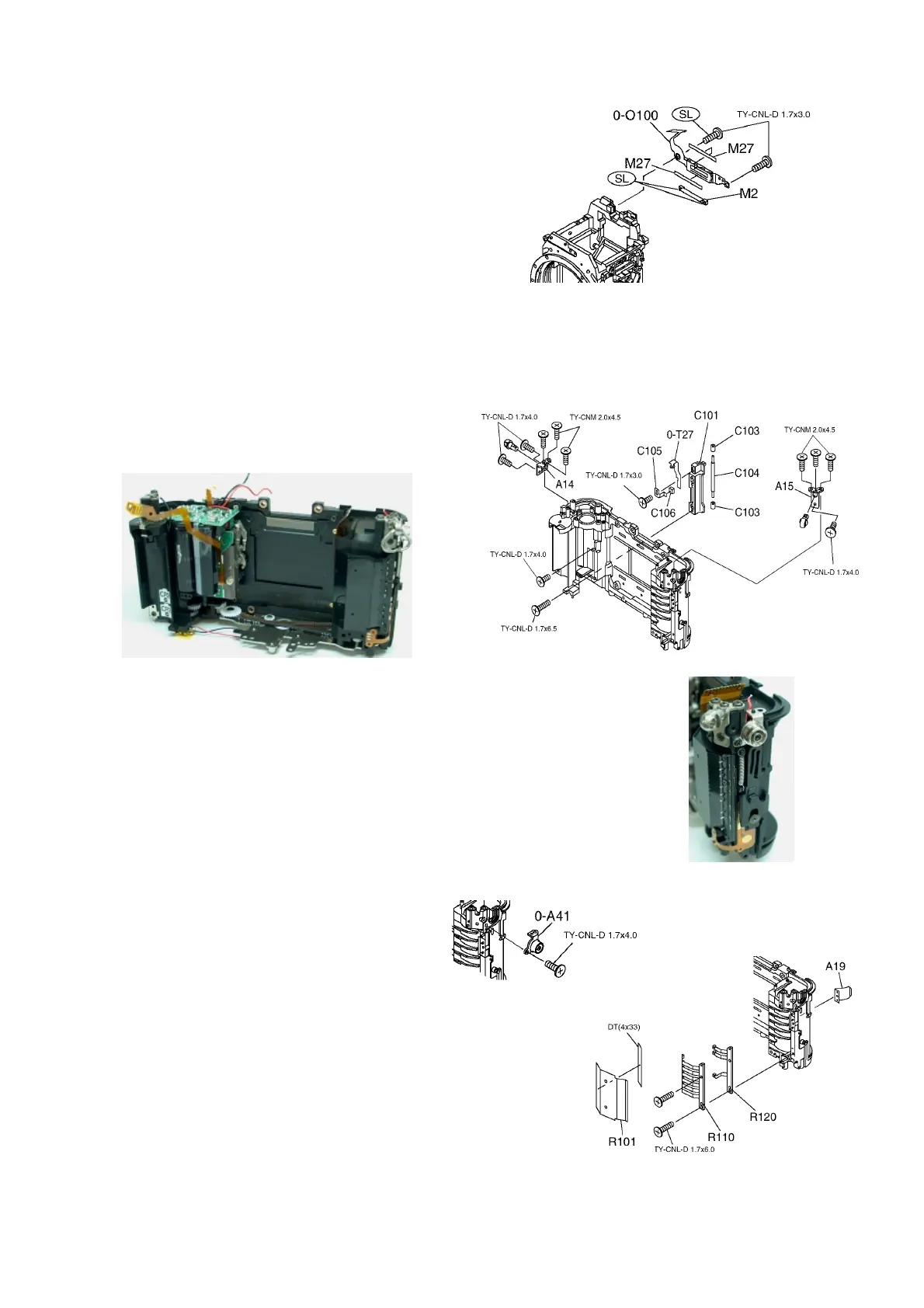
-O100(Bottom LCD block in view finder)
O100(Bottom LCD block in view finder)O100(Bottom LCD block in view finder)
O100(Bottom LCD block in view finder)
1) M2・・・Install securely and apply screw lock
or adhesive bond at 2 positions shown in Fig.
2) 0-O100・M27 x2, 2 Screws.
Tighten temporary. When installing 0-T100,
adjustment of position is required.
5.Disassembly
5.Disassembly5.Disassembly
5.Disassembly
&
&&
&
Assembly of Main Body.
Assembly of Main Body. Assembly of Main Body.
Assembly of Main Body.
[Disassembly procedure]
[Disassembly procedure][Disassembly procedure]
[Disassembly procedure]
[Assembly procedure]
[Assembly procedure][Assembly procedure]
[Assembly procedure]
5
55
5-
--
-1. C101(Reflector base)
1. C101(Reflector base)1. C101(Reflector base)
1. C101(Reflector base)
1) Adhere C106 onto C105 taking care not to overflow.
2) Install photo reflector part of 0-T27 into the
Rectangular hole of C101.
[Note]
[Note][Note]
[Note] Dust, hair and stain should not be exist
on Photo reflector.
3) Install C105 into C101 tightening with screw.
4) Install C103 x2,C104 into C101.
5) [Check]
[Check][Check]
[Check]0-A20 should be installed into main body securely.
6) Insert Flexi. from 0-T27 into rectangular hole on Main body.
7) Install C101 into Main body. 2 screws.(The shorter one on top)
8)[Check]
[Check][Check]
[Check] C103 should turn smoothly.
5
55
5-
--
-2.A14
2.A142.A14
2.A14・
・・
・A15(Strap hook base plate)
A15(Strap hook base plate)A15(Strap hook base plate)
A15(Strap hook base plate)
7screws(From upper side---TY-CNM,
at the Side---TY-CNL-D).
5
55
5-
--
-3.0
3.03.0
3.0-
--
-A41(X terminal base plate)
A41(X terminal base plate)A41(X terminal base plate)
A41(X terminal base plate)
Arrange red lead wire and tighten with 1 screw.
5
55
5-
--
-4.DX contact
4.DX contact4.DX contact
4.DX contact
1) A19・・・Insert into the square hole.
2) R110・R120, 2 screws.
[Check]
[Check][Check]
[Check] When pushing DX contact by tweezers,
contact should not hang on the Main body.
3) Adhere R101 by DT.

 Loading...