27640 -15/34-
3.Main P
3.Main P3.Main P
3.Main P.
..
.C
CC
C.
..
.B
BB
Board
oardoard
oard.
..
.(
((
(0
00
0-
--
-T100
T100T100
T100)
))
)
[Disassembly Procedure]
[Disassembly Procedure][Disassembly Procedure]
[Disassembly Procedure]
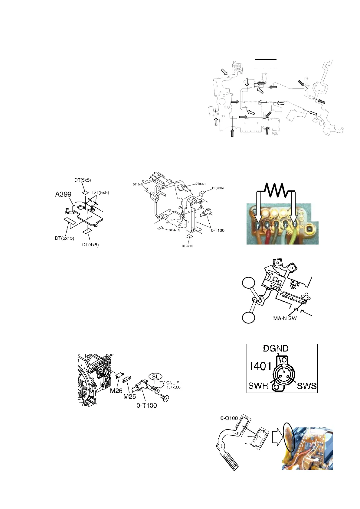
Peel off PT(28x60).and follow the sequence of
assembly procedure in reverse manner.
[Assembly Procedure]
[Assembly Procedure] [Assembly Procedure]
[Assembly Procedure]
3-1.Prepare brand new 0-T100.
1) 3 lead wires(No.8. Yellow・No.9.Purpl・No.24.Black)
2) I401(External release terminal) Solder 3 leads
[Note]
[Note][Note]
[Note] Do not over heat. No space between Flexi.
and terminal should exist.
3) Adhere 5 pcs. of DT・PT(Double stick tape・
Insulation tape) to 5 places.
4) Install A399(Base plate)
5) To check LED position in viewfinder, jump lead wires with resistance and make contact
between MAIN SW land and solder land as shown in figure below.
3
33
3-
--
-2.[Adjust]0
2.[Adjust]02.[Adjust]0
2.[Adjust]0-
--
-T100 LED indication position in view finder.
T100 LED indication position in view finder.T100 LED indication position in view finder.
T100 LED indication position in view finder.
1) M26・M25.
2) Install viewfinder indication temporary.
3) Apply DC5V to the lead wires which were
soldered temporary.
[Note
[Note[Note
[Note]
] ]
] Be careful not to make shortage.
4) Check to see the LED lights on when making contact
between SWS and DGND at external release terminal.
[
[[
[Check
CheckCheck
Check]
]]
]Look out viewfinder and make sure that vignetting,
slant, faulty indication are not exist.
5) [Adjust]
[Adjust][Adjust]
[Adjust] Loosen screw and move finder indication.
6) Apply screw lock on 2 screws.
3
33
3-
--
-3.[Adjust] indicating position of 0
3.[Adjust] indicating position of 03.[Adjust] indicating position of 0
3.[Adjust] indicating position of 0-
--
-O100.
O100.O100.
O100.
1) Align the holes on 0-O100 and 0-T100.
2) Solder 20 soldering lands.
3) Apply DC5V to the lead wires which
were soldered temporary. (All LED should turn on.)
4) Look out viewfinder and make sure that vignetting,
slant, faulty indication are not exist.
5) [Adjust]
[Adjust][Adjust]
[Adjust] Loosen screw and move finder indication.
6) Make sure the tightening of screws and apply screw lock.
1kΩ-2.5kΩ
-
+
◆0-T100
(V)
(Λ)

 Loading...