27640 -3/34-
Procedures
ProceduresProcedures
Procedures
of disassembly & assembly.
1. External Parts.
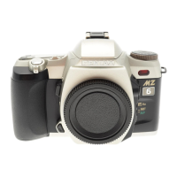
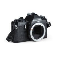
Parts numbers are described based for 27640(Black).
Refer to the Service Parts List for 27641(Silver).
[Note]
[Note][Note]
[Note] To prevent internal electronic circuit from being destroyed by the static electricity,
use anti-static matte and wrist strap.
[Preparation]
[Preparation][Preparation]
[Preparation] Remove eye cap FL, Hot shoe cover FL, Release socket cap, Sync. terminal,
Bottom cover F
L-L,-S.
[Disassembly]
[Disassembly][Disassembly]
[Disassembly]
1
11
1-
--
-1.
1.1.
1.
Bottom cover (A401)
Bottom cover (A401)Bottom cover (A401)
Bottom cover (A401)・
・・
・Battery cap(0
Battery cap(0Battery cap(0
Battery cap(0-
--
-A412)
A412)A412)
A412)
1) Peel off A403(Country seal).
2) Unscrew 5 screws.
3) A401, 0-A412, D204, D205.
1
11
1-
--
-2.
2.2.
2. Top cover
Top coverTop cover
Top cover(
((
(0
00
0-
--
-A301
A301A301
A301)
))
)
1) Unscrew 6 screws •••Bottom side of Flash x1,Inside of
Battery chamber x1, Open back cover x1,
Both side of Eye piece lens x2, Left side of X terminal x1,
Front cover(A102) can be removed.
2) Peel off right hand side of Grip rubber, and remove Grip cover(A159).
Be careful not to make shortage the lead wires which are lying behind A159.
3) Discharge Main capacitor.
Lift top cover and discharge Main capacitor with
resistance of 100~1K.
Blue lead wire : (Xe+)•••On Flash PCB.
A35 Battery contact(-)•••Tightening position of
screw.
4) Red lead wire(No.21,X sync. terminal side)
5) 2 positions on connector(Lift both sides of white
portion for about 2mm, Flexi PCB. will be apart.)
[Note]
[Note][Note]
[Note] The durability of T100 connector is about
40 times. Be sure to handle very courteously.
6) 4 lead wires from Flash PCB(Q200).
7) Peel off PT(28X60)
8) Unsolder 7 lands on 0-T50 Flexi.
9) Remove 0-A301.
 Loading...