27640 -22/34-
5
55
5-
--
-12.0
12.012.0
12.0-
--
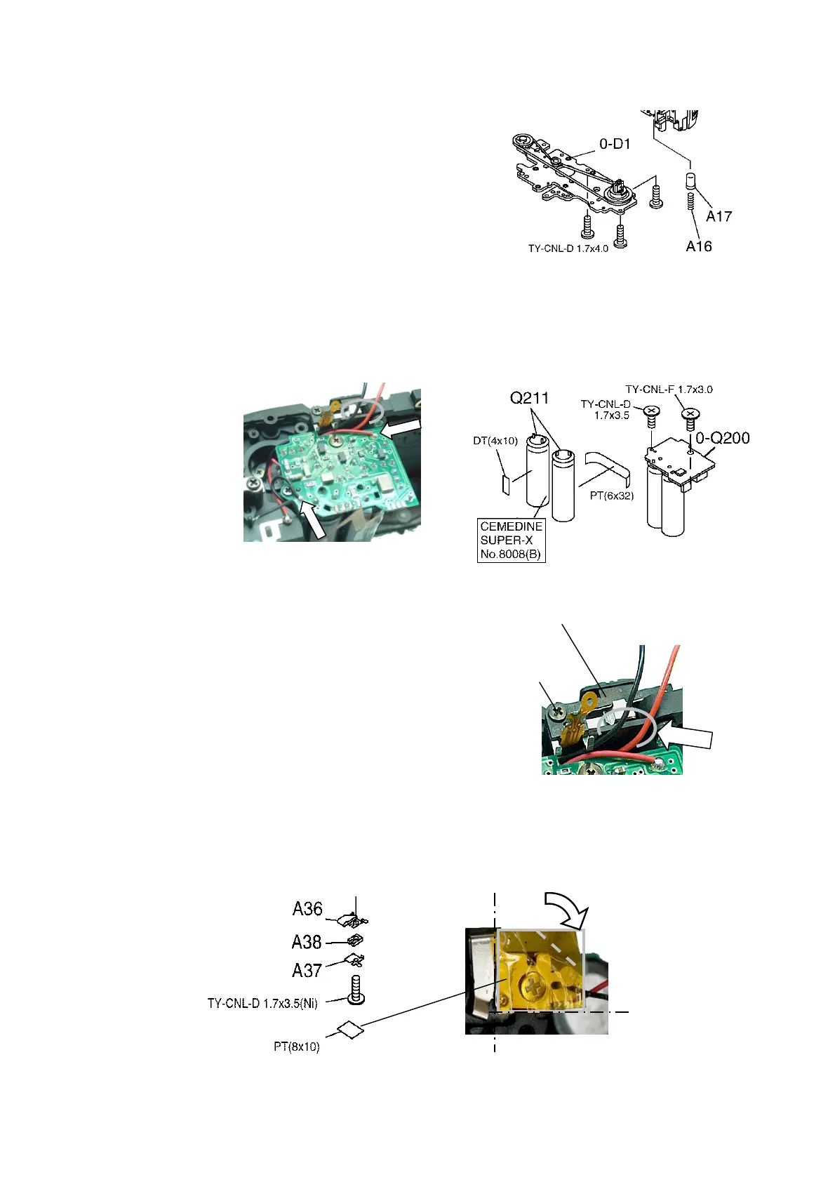
-D1(Bottom base plate)
D1(Bottom base plate)D1(Bottom base plate)
D1(Bottom base plate)
1) A17、A16
2) 0-D1, 3 screws・・・Gear teeth should engage properly.
5
55
5-
--
-13.[Check] Winding
13.[Check] Winding13.[Check] Winding
13.[Check] Winding・
・・
・Rewinding
RewindingRewinding
Rewinding
Apply DC 5.5V to the lead wires of 0-S200,
check the function of winding and rewinding.
5
55
5-
--
-14.0
14.014.0
14.0-
--
-Q200(Flash PCB)
Q200(Flash PCB)Q200(Flash PCB)
Q200(Flash PCB)
1) Twist two leads from Q211 and fix with PT.
2) Apply Super X between Q211.
3) 0-Q200, 2 screws・・・Be careful not to pinch lead wires.
4) 2 lead wires(Red and Black)・・・Solder and arrange lead wires.
5
55
5-
--
-15. 0
15. 015. 0
15. 0-
--
-I240(TV dial
I240(TV dial I240(TV dial
I240(TV dial hold lever
hold leverhold lever
hold lever SW)
SW) SW)
SW)
1) Check the function of SW ON-OFF.
2) 0-I240, 1 screw・・・SW OFF,
Place flexi at the 2 soldering portion.
3) Place 2 lead wires from 0-S200 underneath
the 2 soldering portion.
5
55
5-
--
-16.Battery cover SW and related parts.
16.Battery cover SW and related parts.16.Battery cover SW and related parts.
16.Battery cover SW and related parts.
1) Install as shown in figure.(Be careful the position of PT)
2)[Check]
[Check][Check]
[Check] Make sure that the SW is making proper contact and
A37 has good contact pressure.
0-I240 (A394,A398)
TY-CNL-D
1.7x5.0

 Loading...