27640 -24/34-
6
66
6-
--
-2.Arrange l
2.Arrange l2.Arrange l
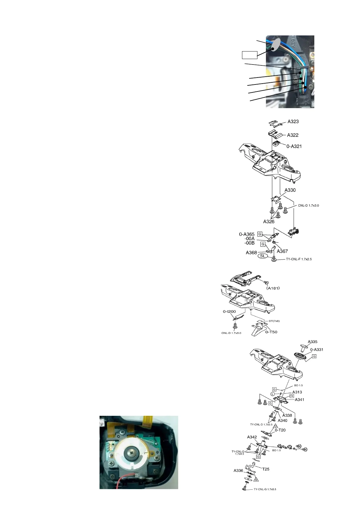
2.Arrange lead wires(Flash should be pop up condition.)
ead wires(Flash should be pop up condition.)ead wires(Flash should be pop up condition.)
ead wires(Flash should be pop up condition.)
1) Slacken 4 lead wires with space for about the size of
one tooth pick and put them into the space in the order
of Blue, Brown, Black, Green from inner side
and should be retained by Q4.
2) Arrange lead wires on DT(7x10) and fix with bond.
6
66
6-
--
-3.A322(Accessory shoe)
3.A322(Accessory shoe)3.A322(Accessory shoe)
3.A322(Accessory shoe)
1)
0-A321,A330・・・Install with CNL-D1.7x3(Rear left side)
and A326 x3. A326 is lock processed screw.:
[Note]
[Note][Note]
[Note] When re-using this screw, apply screw lock.
2) A323(Hot shoe spring)
6
66
6-
--
-4.0
4.04.0
4.0-
--
-A365(F
A365(FA365(F
A365(F.
..
. stopper lever)
stopper lever) stopper lever)
stopper lever)
1) Apply G134 to the 凸 portion of 0-Q3, A368, A301.
2) A367, A368, 1 screw(Apply screw lock).
3) [Check] Check the function of flash pop-up and hooking.
The gap between the top cover and Q1 cover
should be within 0.3mm.
[Assembling procedures
[Assembling procedures[Assembling procedures
[Assembling procedures-
--
-2
22
2]
]]
]
6
66
6-
--
-5. 0
5. 05. 0
5. 0-
--
-I200(Flash SW )
I200(Flash SW )I200(Flash SW )
I200(Flash SW )
1)0-I200, 1 screw.
2)[Check]
[Check] [Check]
[Check] Pop-up the flash while holding by finger and set
free gradually. The SW should turn ON when the screw
head(A181) become visible completely at the side plate.
3).Adhere DT(7x8) onto A301.
4) 0-T50(Hot shoe circuit block)・・・Solder 7 points.
Be careful not to overheat.
5) Adhere 0-T50 with DT(7x8).
6
66
6-
--
-6.0
6.06.0
6.0-
--
-A331(Exposure compensation dial)
A331(Exposure compensation dial)A331(Exposure compensation dial)
A331(Exposure compensation dial)
1) A313,BO1.5
2) 0-A331,A338・A340, 2 screws・・・Apply G134 to indicated in fig.
3) A342,3 screws・・・Apply G151 on the land of 0-T20.
4) A335(AEB dial) and related parts,1 screw, BO 1.5.
・・・Set A335 at ± 0. Apply G151 on the land of T25.
Underneath the protruded parts of A336(inside).
Front portion of tapered part of A345.
DT(7x10)
Bond
Q4
Green
Black
Brown
Blue

 Loading...