27640 -5/34-
1
11
1-
--
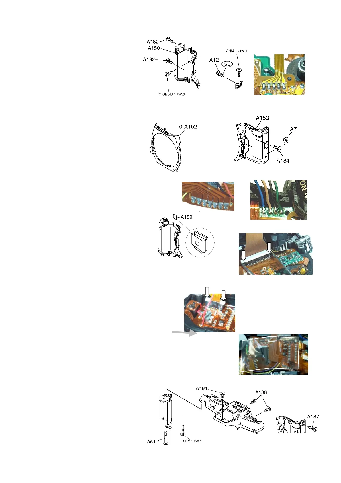
-2. Grip
2. Grip2. Grip
2. Grip(
((
(A150
A150A150
A150)
))
)
1) Solder 5 lands on 0-I230.
2)3 Screws(A182 x2:Size1.7x3.5)
3) A12(Strap hook),1 screw・・・
Apply screw lock at the screw hole.
1
11
1-
--
-3. Back cover assy.
3. Back cover assy.3. Back cover assy.
3. Back cover assy.(
((
(0
00
0-
--
-A201
A201A201
A201)
))
)
1
11
1-
--
-4. Body covering left
4. Body covering left4. Body covering left
4. Body covering left(
((
(A153
A153A153
A153)
))
)
1) A153・A7・・・Set A153 and AF mode SW to the AFS.
2) 1 screw(A184)・・・at the SW side.
1
11
1-
--
-5. Front cover (A10
5. Front cover (A105. Front cover (A10
5. Front cover (A102)
2) 2)
2)
1
11
1-
--
-6.Top cover
6.Top cover6.Top cover
6.Top cover(
((
(0
00
0-
--
-A301
A301A301
A301)
))
)
1) Solder 7 lands (0-T51)
2) Solder 4 lead wires (0-Q100)
(Viewing from rear side---In order Blue,
Brown, Black, Green)
3) Install A159.
4) Solder 2 lands on connector (T25, 0-T67). Insert Flexi.
horizontally and push in both white parts of it.
5) Solder red lead wire
(No.21 Sync. terminal side)
6) Install O-A301.
-1)Arranging lead wire and adhere PT(28x60)→
-2)6 screws(A61=1.7x13, A181=4.7x2.5, A187x3=1.7x5.5)
-3)Adhere A151(Grip rubber) very securely.
1
11
1-
--
-7.Install tempor
7.Install tempor7.Install tempor
7.Install temporally Bottom cover
ally Bottom coverally Bottom cover
ally Bottom cover
and Battery cover
and Battery cover and Battery cover
and Battery cover
for checking and adjustment.
for checking and adjustment.for checking and adjustment.
for checking and adjustment.
0-I230

 Loading...