33
7500 Series Manual
5 Installation and Operation
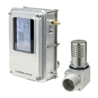
The 7500 series control unit, vent, and manifold can be universally mounted to the customer enclosure. The
7500-01-AA-STD-UNV-PNO is panel-mounted to the enclosure. An included bracket provides a Type 4X /
IPX6 mounting. The7500-MTD-PM... includes the 7500-01... control unit and 7500-MAN-MV-01 mounted
onto a flat panel that is then panel-mounted to the enclosure with the included bracket and gasket for a Type
4X / IPX6 mounting. The 7500-MTD-BX... includes the 7500-01.. control unit and 7500-MAN-MV-01 mounted
onto an enclosure that can then mount externally to the main enclosure. The EPV-7500 vent can be externally
or internally mounted with just the cap showing for exhaust of pressure.
The 7500 system is designed to allow the enclosure to be located in Zone 2 or 22, Class I or II, Division 2
hazardous locations to operate safely by first making them safe internally. This is done either by purging out
the hazardous gas or manually cleaning out the dust hazard and then pressurizing the enclosure so that the
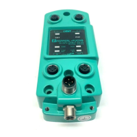
internal pressure prevents the hazardous atmosphere from entering. The 7500 control unit has a differential
pressure sensor within the unit that is pneumatically connected to the protective enclosure to provide
pressure for evaluation of the enclosure pressure and the flow through the enclosure during purging. If
pressure is lost, then power can remain on. An indication by an alarm or display has to notify the operator of
the condition. If the pressurized enclosure has been opened or a positive pressure has not been maintained,
then purging for hazardous gas or cleaning the enclosure out for dust atmospheres is required. The flow
measurement is evaluated by using the pressure in the enclosure and the known measured flow in the tables
through one of the vents selected.
5.1 For Gas Atmospheres
If the protective enclosure has been opened or has been subjected to the hazardous atmosphere, purging
is required to flush out the hazardous gas that may be inside the protective enclosure. A protective gas is
introduced into the enclosure so that the pressure builds up and is exhausted through the enclosure. The
measurement of flow is achieved by the 7500 control unit pressure sensor measuring enclosure pressure
and using that pressure for the flow tables of the vent selected and enclosure size. Each vent has an
enclosure pressure vs. flow table for enclosure size that can be used to determine flow rate. This flow rate is
used to determine the purge time required to make the protective enclosure safe.
Note!
The flow rate tables generated for each vent are measured on a completely sealed enclosure with no
leakage from the enclosure. In real applications, there will be some leakage from the enclosure, which will
depend on the integrity of the seals and door windows, etc. As the enclosure pressure increases, the leakage
may also increase. Always plan on more flow from the protective gas to achieve enclosure pressure because
of the leakage.
After purging, the flow into the enclosure can be reduced so that just a small flow is used for leakage
compensation for pressurization of the enclosure.
5.2 For Dust Atmospheres
If the protective enclosure has been opened or has been subjected to the hazardous atmosphere, the
enclosure must be manually cleaned of all combustible dust, closed, and pressurized before supplying power
to the enclosure. For dust atmospheres, a higher pressure is required for pressurization and is reflected in the
pressure range within the 7500 programming setup.
5.3 For Gas and Dust Atmospheres
Danger!
EN and IEC 60079-2 standards do not state these requirements. Special consideration is needed, and a
proper certification body or authority having jurisdiction must be consulted.