Do you have a question about the Pepperl+Fuchs Absolute Rotary Encoder and is the answer not in the manual?
Outlines the scope of the manual, covering product lifecycle stages from identification to disposal.
Defines the intended users and personnel responsible for product installation and operation.
Explains the various symbols used to convey warnings and important information.
Confirms the product meets European standards and guidelines for development and manufacturing.
Details the meaning of Danger, Warning, and Caution symbols for user safety.
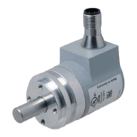
Describes the purpose, functionality, and typical applications of the rotary encoder.
Provides essential safety instructions for installation, operation, and maintenance.
Guides users on how to effectively utilize the manual for encoder setup.
Explains CANopen system features, access methods, and operating modes.
Details the pin assignments and connections for the terminal block.
Explains signal assignments for various connector and cable types.
Instructions for activating the internal bus termination resistor.
Provides guidance on cable connections and signal interference minimization.
Details how to set the node number and baud rate using bus cover switches.
Explains the meaning of the CAN Run and Error LEDs on the bus cover.
Details the signal assignments for magnetic encoders with M12 connectors.
Explains how to activate the internal terminator for magnetic encoders.
Guides on setting node number and baud rate via SDO or LSS.
Steps to configure node number and baud rate for CAN network integration.
How to configure resolution, total resolution, and preset values for the application.
Details the various operational states: Pre-operational, Start-Operational, and Stopped.
Network access and parameter change recommendations in pre-operational mode.
Procedure to set the encoder to the pre-operational network state.
Procedure to set the encoder to the operational network state.
Procedure to set the encoder to the stopped network state.
Steps to reinitialize the encoder if it's not operating correctly.
Describes CAN transmission modes: Polled, Cyclic, and Sync.
Covers parameter storage, list of storable parameters, and saving procedure.
How to restore factory default parameter settings.
Details LSS functionality for node number and baud rate configuration.
Demonstrates setting the encoder's preset value for a desired position.
Details objects within the 1000h-1FFFh range of the CANopen DS301 profile.
Lists objects specific to the manufacturer's implementation.
Lists objects related to application-specific encoder functionalities.
Provides detailed information on object dictionary entries and abbreviations.
Describes the device type and functionality via a 16-bit field.
Used to display internal faults and signal error situations.
Holds error codes signaled via the Emergency Object.
Contains the synchronization message identifier.
Contains the official name of the device.
Contains the article name of the device's circuit board.
Contains the manufacturer's software version number.
Specifies the guard time in milliseconds for network monitoring.
Defines the life time factor for the node guarding protocol.
Used to store device and CANopen parameters to non-volatile memory.
Restores device and CANopen parameters to factory default settings.
Contains the COB-ID for the time stamp object.
Provides a time stamp with a 1µs resolution.
Contains the identifier for the emergency (EMCY) message.
Defines the expected heartbeat cycle time for monitoring.
Specifies the time interval for producing a heartbeat message.
Contains device information such as vendor ID and serial number.
Indicates the date and time of the downloaded configuration.
Specifies how the device behaves in case of errors.
Sets communication parameters for the first transmit PDO.
Sets communication parameters for the second transmit PDO.
Defines the mapping for the first transmit PDO.
Defines the mapping for the second transmit PDO.
Facilitates downloading program data for the bootloader feature.
Contains the encoder's current position value.
Configures code sequence, commissioning, and scaling functions.
Sets the desired number of steps per revolution for the encoder.
Sets the desired total measuring range and resolution for the encoder.
Sets a specific desired position value as the encoder's preset.
Programs a position value to trigger a minimum limit switch event.
Programs a position value to trigger a maximum limit switch event.
Allows storage of custom values for user-defined purposes.
Sets the event timer value for cyclic mode transmission of PDOs.
Stores all parameters to non-volatile memory and executes a device reset.
Provides a high-resolution position value (up to 16/31 bit).
Sets the unique network node number for the device.
Sets the communication baud rate for the CAN network.
Activates the internal galvanic isolated bus terminator.
Controls automatic detection of the CAN network baud rate.
Defines the encoder's start-up behavior without NMT commands.
Configures speed measurement, units, and filtering.
Contains the calculated speed value of the encoder.
Sets acceleration control parameters.
Contains the acceleration value (not supported by this device).
Configures the device for backward compatibility with older systems.
A diagnostic counter for monitoring position value updates.
Provides a time stamp for when the position value was measured.
Controls the bootloader functionality, including device reset.
Controls the incremental resolution per revolution (pulses/channel).
Configures the phase shift between channels A and B.
Sets code sequence, commissioning, and scaling functions for the encoder.
Specifies the number of distinguishable steps per revolution.
Specifies the total number of distinguishable steps over the measuring range.
Indicates the preset value for the output position.
Contains the encoder's current process value.
Provides a high-resolution position value (up to 16/31 bit).
Contains the measured speed value of the encoder.
Contains the acceleration value of the encoder.
Sets the cyclic timer value for corresponding TPDOs.
Contains the cam state register for channels 1 through 254.
Contains the register for enabling cam functions.
Contains the register for setting cam polarity.
Provides the actual area status of the encoder position.
Indicates the position value for flagging work area underflow.
Indicates the position value for flagging work area overflow.
Provides information on the encoder's internal programmed parameters.
Contains the physical measuring steps per single revolution.
Contains the number of distinguishable revolutions of the encoder.
Provides alarm messages for detected malfunctions.
Lists all alarms supported by the device.
Provides warnings for exceeded internal parameter tolerances.
Lists all warnings supported by the device.
Provides encoder profile and manufacturer software versions.
Indicates the total operating time of the device.
Contains the offset value, calculated by the preset function.
Provides manufacturer-specific module identification.
Contains the unique serial number of the device.
A checklist to diagnose and resolve common encoder faults.
| Type | Absolute |
|---|---|
| Interface | SSI, CANopen, PROFIBUS, Ethernet |
| Housing Material | Aluminum, Stainless Steel |
| Protection Class | IP67 |
| Operating Temperature | -40°C ... +85°C (depending on model) |
| Voltage Supply | 10 ... 30 V DC, 5 V DC (depending on model) |
| Shaft Diameter | 6 mm, 10 mm |