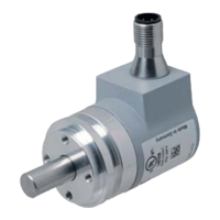
Absolute Rotary Encoder
3
1 Introduction................................................................................. 8
1.1 Content of this Document ................................................................... 8
1.2 Target Group, Personnel...................................................................... 8
1.3 Symbols Used ...................................................................................... 8
2 Declaration of conformity ........................................................ 10
2.1 CE conformity..................................................................................... 10
3 Safety ......................................................................................... 11
3.1 Symbols relevant to safety................................................................ 11
3.2 Intended Use ...................................................................................... 11
3.3 General safety instructions ............................................................... 11
4 General Information on System Integration ........................... 12
4.1 Using this Manual .............................................................................. 12
4.2 General CANopen Information .......................................................... 12
5 Installation of Photoelectric Absolute Rotary Encoder ........ 14
5.1 Signal Assignment of Terminal Block .............................................. 14
5.2 Signal Assignment of Connector and Cable Variants .................... 16
5.3 Activation of the Terminator.............................................................. 17
5.4 Installation Hints for Cabling ............................................................ 17
5.5 Setting of Node Number and Baud Rate in the Bus Cover ............ 17
5.6 Status of the Bus Cover LEDs........................................................... 19
6 Installation of Magnetic Absolute Rotary Encoder ............... 21
6.1 Signal Assignment of Connector and Cable Variants .................... 21
6.2 Activation of Terminator .................................................................... 21
6.3 Setting of Node Number and Baud Rate.......................................... 21
6.4 Status of the LEDs.............................................................................. 22