7. Operating the IVIS
®
Spectrum
40
2. Open the imaging chamber door to see the alignment grid projected by the
laser/galvanometer on the imaging platform
(Figure 7.5).
— The field of view (FOV) setting defines the size of the squares in the
alignment grid.
3. To change the size of the squares in the alignment grid, select a different
FOV setting.
For example FOV settings, see Figure 6.4, page 28.
The alignment laser turns off after 60 seconds. Repeat step 1 to turn on the
laser.
4. Using the alignment grid as a guide, place the specimen(s) at the locations
of interest, then proceed with image acquisition.
The Living Image® software controls the photographic illumination LED
intensity.
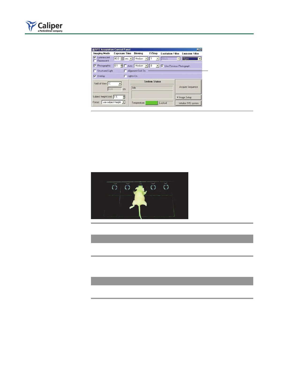
Figure 7.4 IVIS System Control panel
Figure 7.5 Laser alignment grid
To display the alignment
grid, choose Alignment
Grid On.
 Loading...