46 SEBU8605-01
Operation Section
Engine Diagnostics
Engine Diagnostics
i02651093
Self-D iagn ost ics
Perkins electronic engines have the capability to
perform a self-diagnostics test. When the system
detects an active problem, a diagnostic lamp
is activated. Diagnostic codes will be stored in
permanent memory in the Electronic Control Module
(ECM). The diagnostic codes can be retrieved
by using the electronic service tool. Refer to
Troubleshooting , “Electronic Service Tools” for
further information.
Some installations have electronic displays that
provide direct readouts of the engine diagnostic
codes. Refer to the manual that is provided
by the OEM for more information on retrieving
engine diagnostic codes. Alternatively refer to
Troubleshooting , “Indicator Lamps” for further
information.
Active codes represent problems that currently exist.
These problems should be investigated first.
Logged codes represent the following items:
•
Intermittent problems
•
Recorded events
•
Performance history
The problems may have been repaired since the
logging of the code. These codes do not indicate that
a repair is needed. The codes are guides or signals
when a situation exists. Codes may be helpful to
troubleshoot problems.
When the problems have been corrected, the
corresponding logged fault codes should be cleared.
i02651107
Diagnostic Lamp
A diagnostic lamp is used to indicate the existence of
an
active fault. Refer to Troubleshooting , “Indicator
Lamps” for more information. A fault diagnostic
code will remain active until the problem is repaired.
T
he diagnostic code may be retrieved by using the
electronic service tool. Refer to Troubleshooting ,
“Electronic Service Tools” for more information.
i04215570
Diagnostic Flash Code
Retrieval
Use the “DIAGNOSTIC” lamp or an electronic service
tool to determine the diagnostic flash code.
Usethefollowingproceduretoretrievetheflash
codes if the engine is equipped with a “DIAGNOSTIC”
lamp:
1. Move the keyswitch from the on/off two times
within3se
conds.
A flashing YELLOW lamp indicates a 3-digit code for
the engine
. The sequence of flashes represents the
system diagnostic message. Count the first sequence
of fl ashes in order to determine the first digit of the
flash code
. After a two second pause, the second
sequence of flashes will identify the second digit of
the flash code. After the second pause, the third
sequenc
eofflashes will identify the flash code.
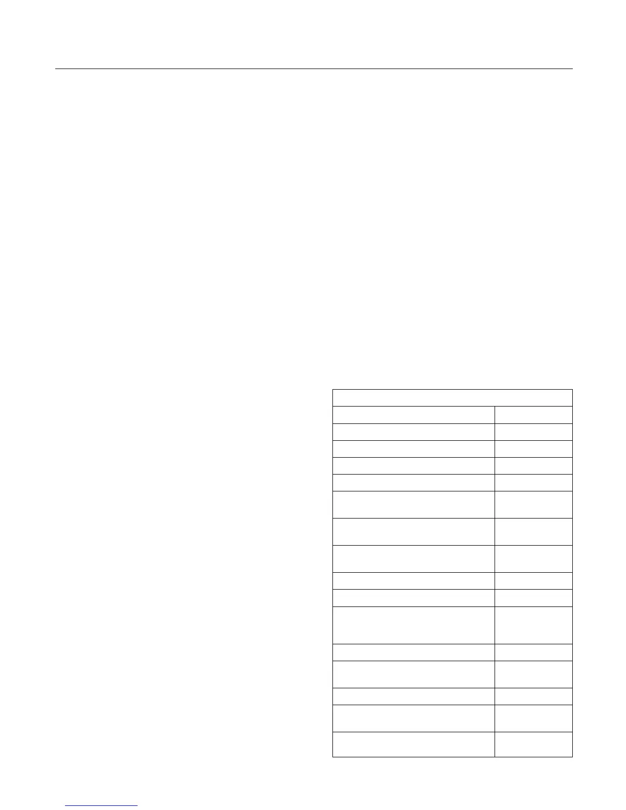
Table 3
Flash Code Table
Description
Flash Code
Injector fault
111
Injector number 2 current out of range
112
Injector number 3 current out of range 113
Injector number 4 current out of range 114
Injector number 5 current out of range
(6 cylinder only)
115
Injector number 6 current out of range
(6 cylinder only)
116
Intake manifold air temperature
sensor out of range
133
Engine speed sensor out of range
141
Engine timing offset fault
143
Engine operation mode selector
switch erratic, intermittent, or
incorrect
144
High air filter restriction - Warning
151
Atmospheric pressure sensor out of
range
152
Throttle position sensor out of range 154
Secondary throttle position sensor
out of range
155
Oil pressure sensor out of range
157
(continued)