1204F - DEF System Supplement
2.10 DEF tank coolant supply lines
• Only the designated coolant supply and return ports on the engine may be used as detailed
in section 5.2.1
• The correct hose fittings must be used to connect to the engine; ref section 5.2.1
• The correct hose fittings must be used to match the DEF coolant valve; ref section 5.2.1
• Reinforced hose must be used to minimise expansion when system is pressurised
• To achieve adequate thaw of the DEF tank a minimum of 2l/min coolant flow and temp of
80°C temp must be maintained. To ensure sufficient flow the following requirements must
be met:
• The total length of the coolant hoses (supply and return from tank) must be less than
8m, including a maximum of two 90° hose fittings.
• Use connectors and hoses with ID 16mm (5/8”).
• The maximum volume of coolant in the DEF tank coolant supply line must be such that:
For a Portrait tank
CV (
litres) + 0.4 (litres) < RV (litres)
For a Landscape tank
CV (
litres) + 0.6 (litres) < RV (litres)
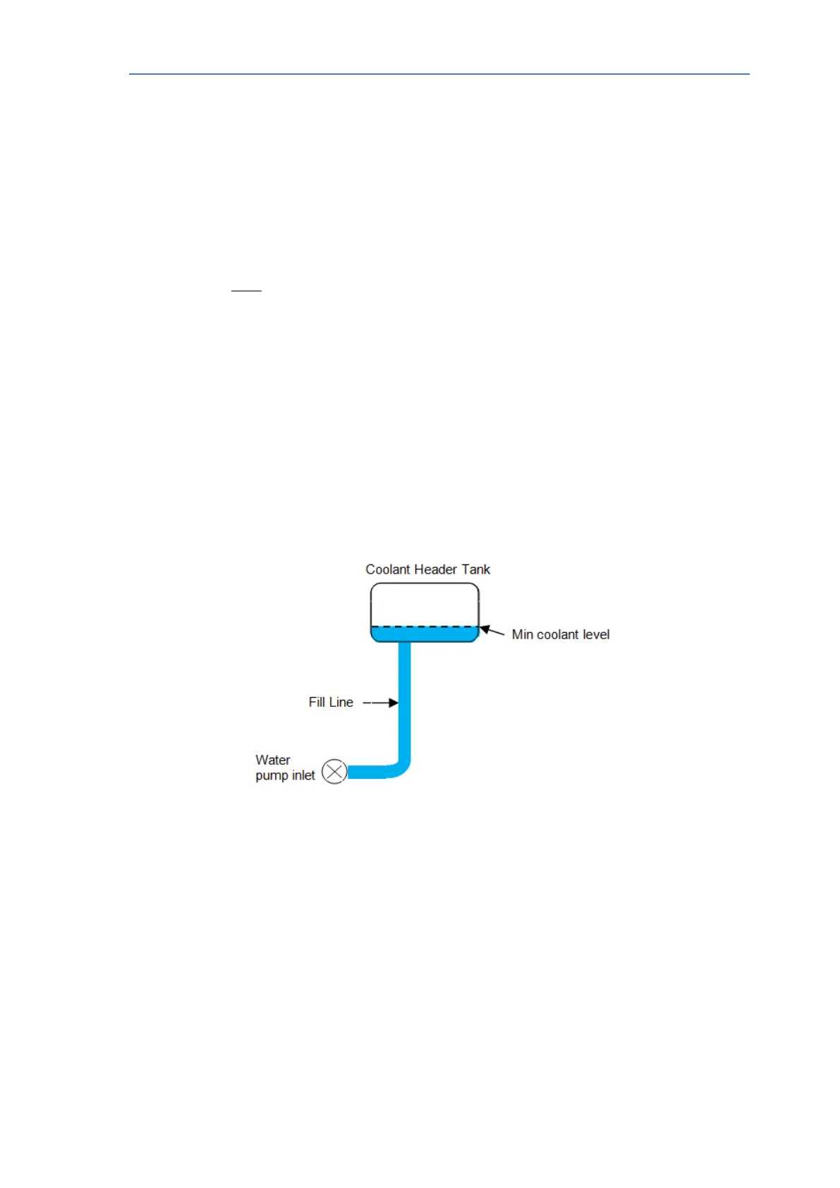
Where
CV = Coolant Volume - the volume of coolant in DEF tank coolant supply line
RV = Reserve Volume - this is equal to the volume of coolant below the
minimum level in the coolant header tank added to the volume of coolant in
the fill line as shown in the diagram below.
• The coolant lines must:
• Be properly supported
• Not impose stress on the mating connectors
• Recommend support 150mm-250mm max from end connectors
• Be secured such as to avoid abrasion with touching surfaces
• Have minimal bends
• The coolant temperature drop (delta) between engine coolant temperature sensor and DEF
tank temperature sensor must not exceed 10°C.
A&I manual Publication TPD 1832 – Production issue 3. Page 14 of 41