1204F - DEF System Supplement
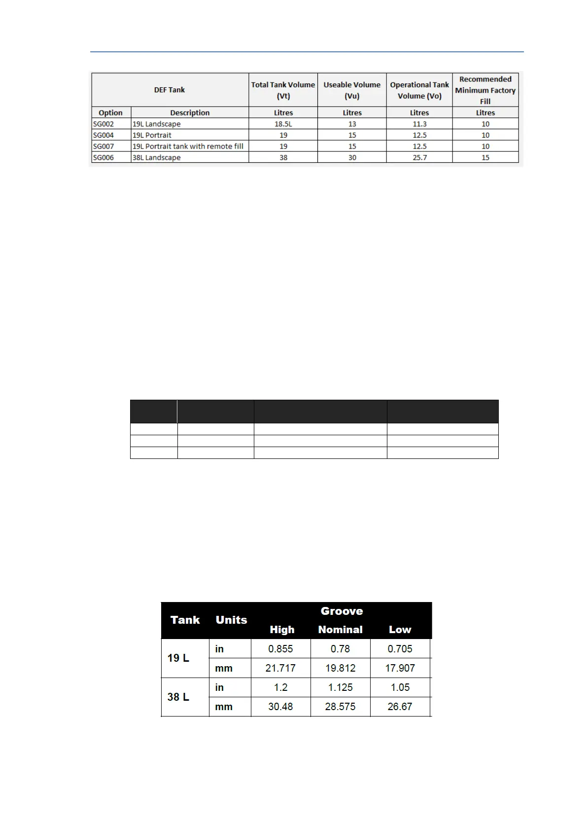
Table 5.4 - DEF tank Volumes
5.4.2 DEF Tank Mounting and Installation
• The DEF tank should be located to avoid heat sources or stagnant hot air build up which
will lead to overheating of the DEF.
• Proper distance and elevation from DEF injector –ref 5.4
• Ease of tank drain
• Ease of filling with care taken regarding spillage
• Tank fill vent away from HVAC air intake (unpleasant odor in cab may result)
• Out of direct sunlight preferred
• The tank must be +/-5° from horizontal when filling with DEF
• An anti-friction mat is recommended under the tank base.
• Table 5.5 below details the weight of the Standard DEF tank options when filled with DEF
to 100% full.
Weight (g) – 100%
DEF fill level
Table 5.5 – DEF Tank Mounting Details
5.4.3 DEF Tank Straps
• The Perkins supplied DEF tanks feature grooves to help locate the tank straps. The groove
tolerances are shown in table 5.6 below. The Mandatory requirements are detailed in section
2 and must be adhered to.
• The strap design must consider both the static assembled conditions plus the loads from
machine operation that are typically used as design points for a given machine. It is
recommended that FEA is conducted on the tank and mounting design.
Table 5.6 – DEF Tank Groove Tolerances.
A&I manual Publication TPD 1832 – Production issue 3. Page 35 of 41