1204F - DEF System Supplement
• All DEF tanks held down by straps must have their base fully supported by a structural
platform. Full support is defined as a continuous material that is at least as large as the tank's
base dimensions. Structural is defined as being able to support full tank mass with
application load without plastic deformation or failure
• The use of an Anti-Friction rubber mat under the tank base is recommended. Inadequate
clamp loads and / or insufficient coefficient of static friction, between the tank and mounting
surface, can allow the tank to slip under extreme conditions. It is recommended that either
60 or 70 durometer 2mm thick rubber may be used. This is a chloroprene rubber, appropriate
for DEF, with temperature range between -40°C and 100°C.
• Any metallic surfaces contacting the tank should be free of burrs, weld splatter, sharp edges.
• The tank straps require a preload when installed. Thermal expansion and contraction of the
tank may loosen the straps if a preload is not applied. The magnitude of the preload is a
balance between enough preload to form the strap, to resist slip, preventing excessive plastic
deformation of the tank and having adequate life for the components. It is recommended
that a study be conducted to understand preload impacts and that care must be taken during
assembly to ensure that excessive preload is not applied. At assembly, a new, unformed
flat strap undergoes permanent yielding or deformation when bending around the tank
corners
• The DEF tank strap should lie flat in the strap groove incorporated into the tank to help keep
the strap in place.
• Having a locked joint is a requirement. This can be accomplished by using either a jam or
lock nut.
• The strap should be long enough to support the bolt dimensions. If there is not enough free
bolt length assembly may be difficult.
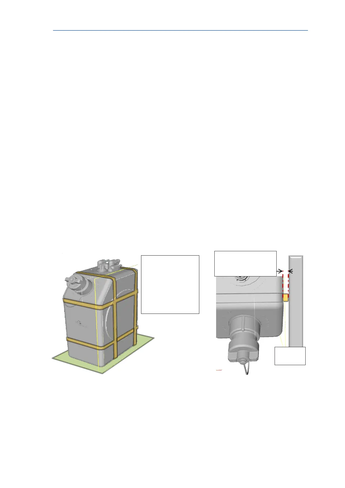
Fig 5.7 – DEF Tank straps
only be located in moulded
grooves (orange)
All other side and top faces
(grey) must have 9mm
minimum clearance to
machine components.
Base to be supported by a
flat surface (green)
chassis/bulk
all sides can be created with
thick spacers/straps in
grooves
A&I manual Publication TPD 1832 – Production issue 3. Page 36 of 41