1204F - DEF System Supplement
• There must be a minimum of 150mm clearance above the filter cap to provide sufficient
space to service the filter.
o Access for a 22mm hex socket is required to replace the filter cap (to 14Nm +/-
2Nm)
• Minimum clearance of 125mm must be given for DCU connector removal
• Minimum clearance of 65mm must be given for DEF inlet and outlet connector fit/removal
• Minimum clearance of 25mm should be given to the left and right side of the PEU
• The pump must be specified to the correct voltage of the machine and wired in accordance
with the Electronic A&I manual
• There is an M8x1.5 tapping (21mm depth) on the RHS top face of the DCU which should
be used for strain relief of the electrical harness. Torque limit is 15Nm=/-1.5Nm.
• The PEU must not be painted
2.8 DEF component relative positions
• All DEF system configurations require validation and approval to ensure the system
requirements are met.
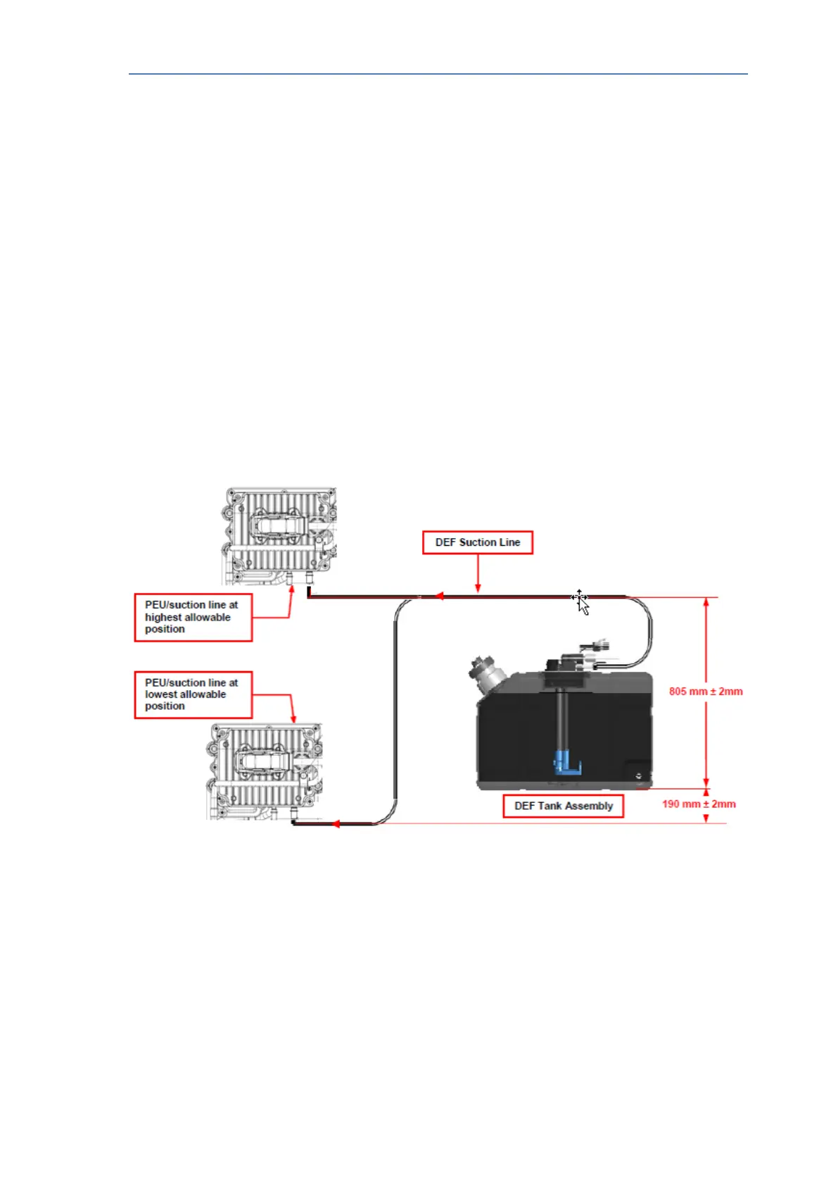
2.8.1 DEF tank to PEU
There are limitations on the relative position of the tank base level to the PEU inlet
connection; these are detailed in fig 2.3 below.
Fig 2.3 – DEF Tank Relative Position to PEU
• The longest DEF suction line allowed is 2000 mm
• The lowest point on the DEF suction line, which attaches to the PEU, should be no more
than 190 mm ± 2 mm lower than the bottom of the standard tank.
• The highest point on the DEF suction line, which attaches to the PEU, should be no more
than 805 mm ± 2 mm higher than the bottom of the standard tank.
A&I manual Publication TPD 1832 – Production issue 3. Page 11 of 41