1204F - DEF System Supplement
5.2.1 Coolant Connections
Coolant must be supplied from the engine to the DEF tank header in order to heat the DEF in cold
conditions. The coolant is supplied via the coolant valve which is controlled via the DCU.
Coolant is taken from the coolant outlet on the engine to the coolant valve, then to the tank header,
returning directly back to the engine at the water pump inlet.
The table below outlines locations specifically for this purpose. If you wish to feed and return coolant
using ports normally reserved for cab heater connections please contact your applications engineer.
Table 5.2 – Coolant connection Details
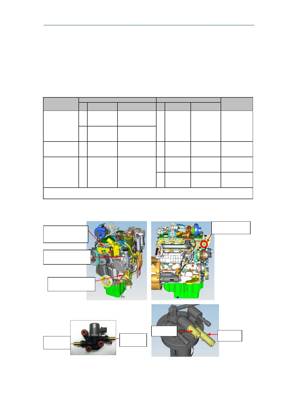
See below Fig 5.2 for identification of acceptable location to use on the engine for feed and return.
Fig 5.2 – Coolant connections locations
Line
Recommended
Diameter
# Size Connection point # Size
Engine Coolant
feed to Coolant
Valve
A
STOR (ISO
Top centre
cylinder head
C
5/8” OD
for push fit
hose
Coolant
Valve Inlet
5/8”
(15.8mm) ID
B
STOR (ISO
Left front side of
cylinder head
Coolant Valve
to Tank Header
D
5/8” OD for
push fit hose
Coolant Valve
outlet
E
for push fit
Tank Header
coolant inlet
5/8”
(15.8mm) ID
Tank Header
Return to
Engine
F
5/8” OD for
push fit hose
Tank Header
coolant outlet
G
½” – 14
NPSI
pump
5/8”
(15.8mm) ID
H
5/16” -12
STOR
line
5/8”
(15.8mm) ID
Total hose length must not exceed 8000mm, this may include 90° fittings at each end.
Additional fittings within this line length will reduce acceptable line length.
Feed
(out of cylinder head)
Return (into top of water
Coolant Return
Coolant valve feed
Valve inlet
Valve Outlet
A&I manual Publication TPD 1832 – Production issue 3. Page 29 of 41