Set-up and Initial Commissioning
22
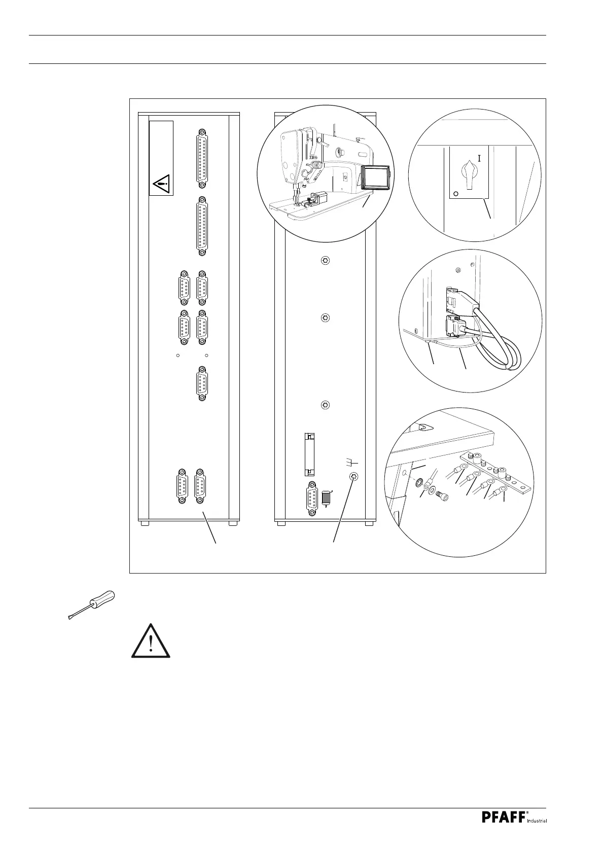
Fig. 8 - 04
8.02 Connecting the plug-in connections and ground cable
O Insert all plugs on the control box 2 in accordance with their designation.
O Insert the "motor" into the bushing X 3 and the bushing X 8.
Caution
Inserting the plug incorrectly can damage the control unit!
O Attach the following ground cables in order to discharge static electricity.
O Securely attach the ground cable from the sewing head 1 to ground point A.
O Securely attach the ground cable from the control point B to ground point B.
O Securely attach the ground cable from the main switch 3 to ground point C.
O Securely attach the ground cable from the stand 4 to ground point D.
O Securely attach the ground cable 5 from the motor to ground point E.
X15
Fadenwächter
X11/A
CAN-BUS
X11/B
Sollwertgeber
X1/A
RS 232/1
X1/B
SSI
Eingänge
X5
Ausgänge
X13
ATTENTION
Danger of exchange
ACHTUNG
Vertauschungsgefahr
X3
X8
Motor
X4/A
SM2
X4/B
SM1
B
2
5
E
1
0
3
A
B
C
D
4
D
 Loading...