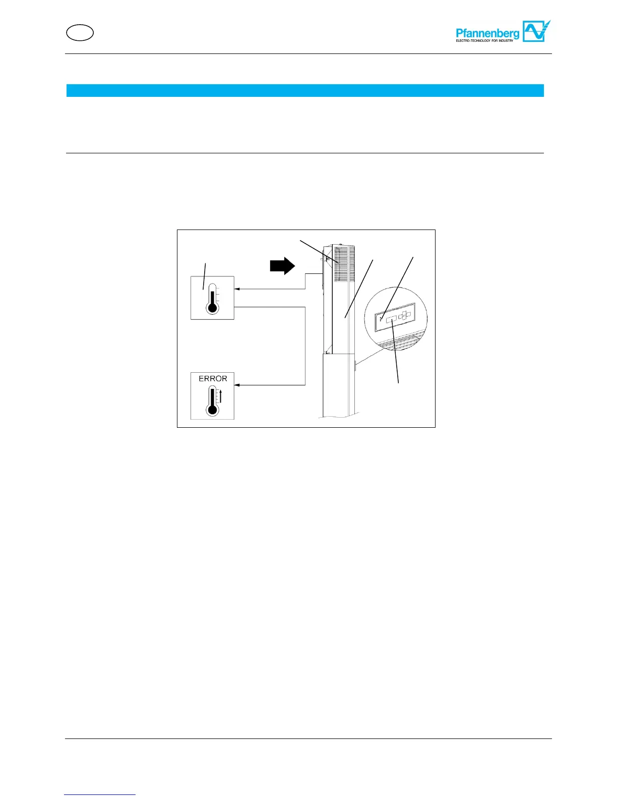
The Multi-Controller (MC) has a control panel with a green LED light (1). If an error occurs, the green LED light (1)
blinks and various system information is displayed in the LCD (5); see system information .
If assembly and installation are completed, switch on the power supply to the cooling unit.
The cooling unit starts its operation and the LED light (1) illuminates green continuously.
After the supply voltage has been connected and the door is closed, the units run continuously.
Exception: Energy-saving mode and cooling units with anti-freeze option.
The external temperature sensor controls the energy-saving mode; see TS2 temperature sensor.
The Multimaster function can connect up to six cooling units in the bus function.
The LCD (5) displays the current operating statuses; see System information.
The cooling unit (2) is equipped with an electronic control unit. An internal temperature sensor (4) detects the
temperature of the air sucked in from the interior of the switch cabinet (3). If the upper or lower limit temperature
is exceeded or undercut, a fault indication is triggered.
The green LED light (1) blinks and the LCD (5) displays the error number with temperature (°C/°F).
The ambient conditions and switch cabinet interior temperatures must correspond to the prescribed technical
data; see Technical data.
The ambient temperature must be less than 55°C; see Air flow functional principle.