The film for DTI cooling units with assembly instructions is available HERE.
Switch cabinet assembly
Requirements
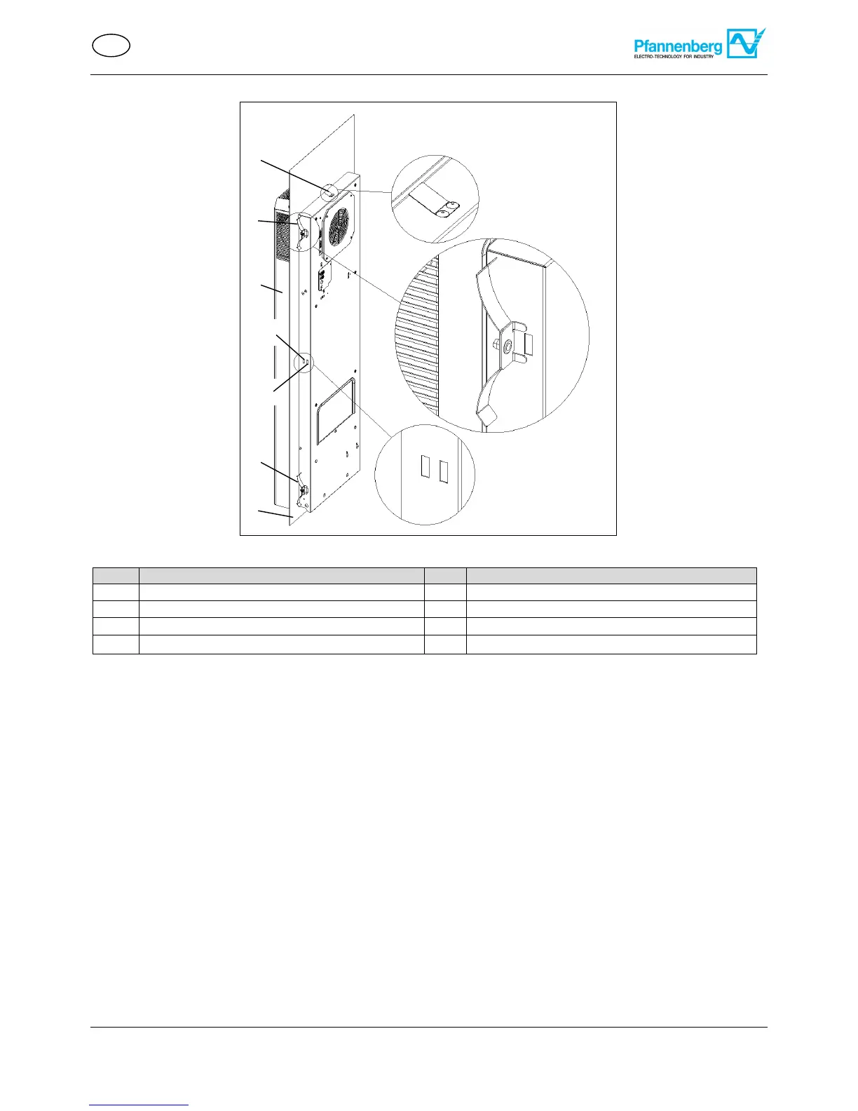
- The cut-out for the DTI cooling unit has been made; see the figure DTI cooling unit assembly.
- The cooling unit is de-energized.
Required tools and material
- Assembly tool, fastening springs (2)/(5) (accessory kit)
Procedure
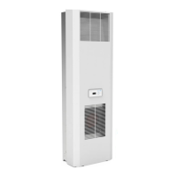
Fit the cooling unit (3) in the cut-out from outside; see the figure DTI cooling unit assembly.
Push the cooling unit (3) into the switch cabinet (6) until the unit seal is applied.
The catch spring (1) on the top side of the unit audibly engages. The cooling unit (3) is now secured from falling
out.
Engage the fastening springs (2)/(5) on the inside of the switch cabinet (6).
Press the fastening springs in with your hand so that the retaining bracket engages in the housing cutout (4 A).
Use the fastening springs in the rear housing cut-outs (4B) for switch cabinets with reinforcement frame.
Mount the cooling unit (3) so that the emergency condensate drain is arranged at the bottom of the unit.
The DTI cooling unit is attached to the switch cabinet and ready for Electrical connection.