10 085 408 164
CAUTION:
If there is excessive condensate during normal operation
check the sealings of the switch cabinet.
We recommend that you install a door contact switch to
switch off the cooling unit, when the door of the switch ca-
binet is opened, in order to prevent excessive condensate.
8 Installation
8.1 General
• Theinstallationplacefortheswitchcabinetmustbeselected
such that proper ventilation of the cooling unit is ensured.
• Thesingleunitsortheunitsandthewallmustbeatadistance
of 200 mm at least.
• Aircirculationintheswitchcabinetmustnotbeimpededby
built-in parts.
• Theassemblyofthecoolingunitcanbecarriedoutwithand
withoutacover(external).(Theunitmustbedisconnected
fromthepowersupply!)
• Thesiteofinstallationmustbeprotectedagainstcontamination.
CAUTION
If the cooling unit is mounted on an switch cabinet door, it
mustbeconrmedthatthehingescansupporttheadditional
weight or that the switch cabinet will not topple over when
the door is opened
CAUTION: Chips may damage the switch cabinet.
If the required cutouts are only made in the switch cabinet
just before mounting of the cooling unit, make sure that swarf
is not allowed to enter the device hood by using a cover
sheet, for example.
Hint
To facilitate installation with heavy units, M8 lifting eyes can be
screwedintotheupperxingontheequipmenthousing.Simple
„onemaninstallation“istherebypossible.
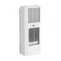
8.2 Installation of side-mounted, bolt-on cooling unit
DTS
The mounting surface of the switch cabinet is to be provided with
cutout(s)andholesforairventilationopeningsandforsecuringthe
unit according to the accompanying sheet.
The drawing on the accompanying sheet also shows the location of
the electrical connections and ventilation openings.
1) Makecutout(s)anddrillingsforthecoolingunit,ifnotalready
providedintheswitchcabinet(seedrawingonaccompanying
sheet).
Remove burrs from the cut edges
2) Positiontheprolesealaroundtherimofthecutou(s)t.Position
the seal so that the impact ends are facing downwards.
3) Screwthetwothreadedstudsincludedinthecomponentpack
intotheupperxingpointofthecoolingunit.Suspendtheunit
from outside onto the switch cabinet using the threaded studs.
4) Usethescrews,nutsandwashersincludedinthecomponent
pack to secure the cooling unit on the inner side of the switch
cabinet.Tightenupxingssothatthesealiscompressedtoa
thickness of 2 mm.
5) Feedthecondensaterun-offtubethroughtheopeninginthe
base of the unit. Lay the tube with a downward fall. Shorten as
required.
6) Ifthecoolingunitismountedwithoutthedevicehood,plugthe
earth cable and the connecting cable to the display unit on the
hood and mount this on the cooling unit.
7) Clampthecableasshownintheconnectiondiagram(seeback
ofunit)totheplug(componentpack)andconnecttotheunit.
-conductersize:0,5–2,5mm²orAWG20-AWG14(Intheselec-
tionofcablesize,therelevantregulationsmustbeobserved!)
8) Connecttheunittotheelectricalsupply(seeSection8.4).
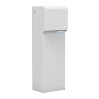
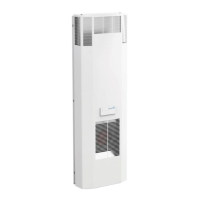
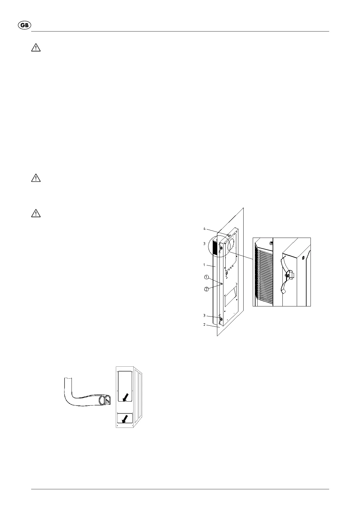
8.3 Installation of built-in cooling unit DTI
The mounting surface of the switch cabinet is to be provided with a
rectangular cutout as shown on the accompanying sheet.
The drawing on the accompanying sheet shows the location of the
ventilation openings after mounting the unit as seen from the inside
of the switch cabinet.
1) Makecutoutforthecoolingunit,ifnotalreadyprovidedinthe
switchcabinet(seedrawingonaccompanyingsheet).
Remove burrs from the cut edges
2) Fromtheoutside,insertthecoolingunit(Pos.1)intothecutout
and push through until the unit seal engages with the switch
cabinet (Pos. 2). Close the snap-fasteners (Pos.4) with an
audible click from the unit or upper side and secure the unit
against falling out.
1 CoolingUnitDTI
2 Switch cabinet wall or door
3 Securing spring
4 Snap fastener
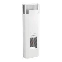
3) Ontheinsideoftheswitchcabinet,makesurethatthesecuring
springs(Pos.3)suppliedinthecomponentpackrestintheir
locations. To do this, compress the springs by hand so that the
securing bracket can be secured in the housing cutout.
In switch cabinets with reinforcing frames, insert the securing
springs in the rear of the housing cutouts.
4) Feedthecondensaterun-offtubethroughtheopeninginthe
base of the unit. Lay the tube with a downward fall. Shorten as
required.
5) Ifthecoolingunitismountedwithoutthedevicehood,plugthe
earth cable and the connecting cable to the display unit on the
hood and mount this on the cooling unit.
6) Clampcablesinaccordancewiththeconnectiondiagram(see
rearofunit)totheplug-inconnectors(enclosedpackage)and
connect to the unit.
- lead cross-section: 0.5 – 2.5 mm², and/or AWG20 – AWG14
(fortheselectionofthecablecross-sectiontherelevantprovi-
 Loading...