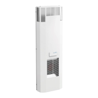
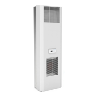
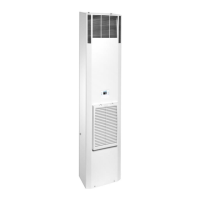
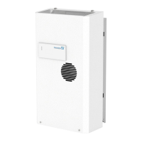
085 408 164 11
sionsaretobetakenintoaccount).
7)Connectthecoolingunittothepowersource(seesection8.4).
8.4 Power connection
CAUTION:
• Thecoolingunitmustbeconnectedtothemainsbymeansofa
disconnecting device with a contact gap of at least 3 mm when
switched off.
• Notemperaturecontrolmustbeseries-connectedtothecooling
unit feed.
The fuse as indicated on the ID plate must be series-connected
as line protection.
• Powerconnectionandrepairs,ifapplicable,mayonlybecar-
ried out by authorized trained electricians.
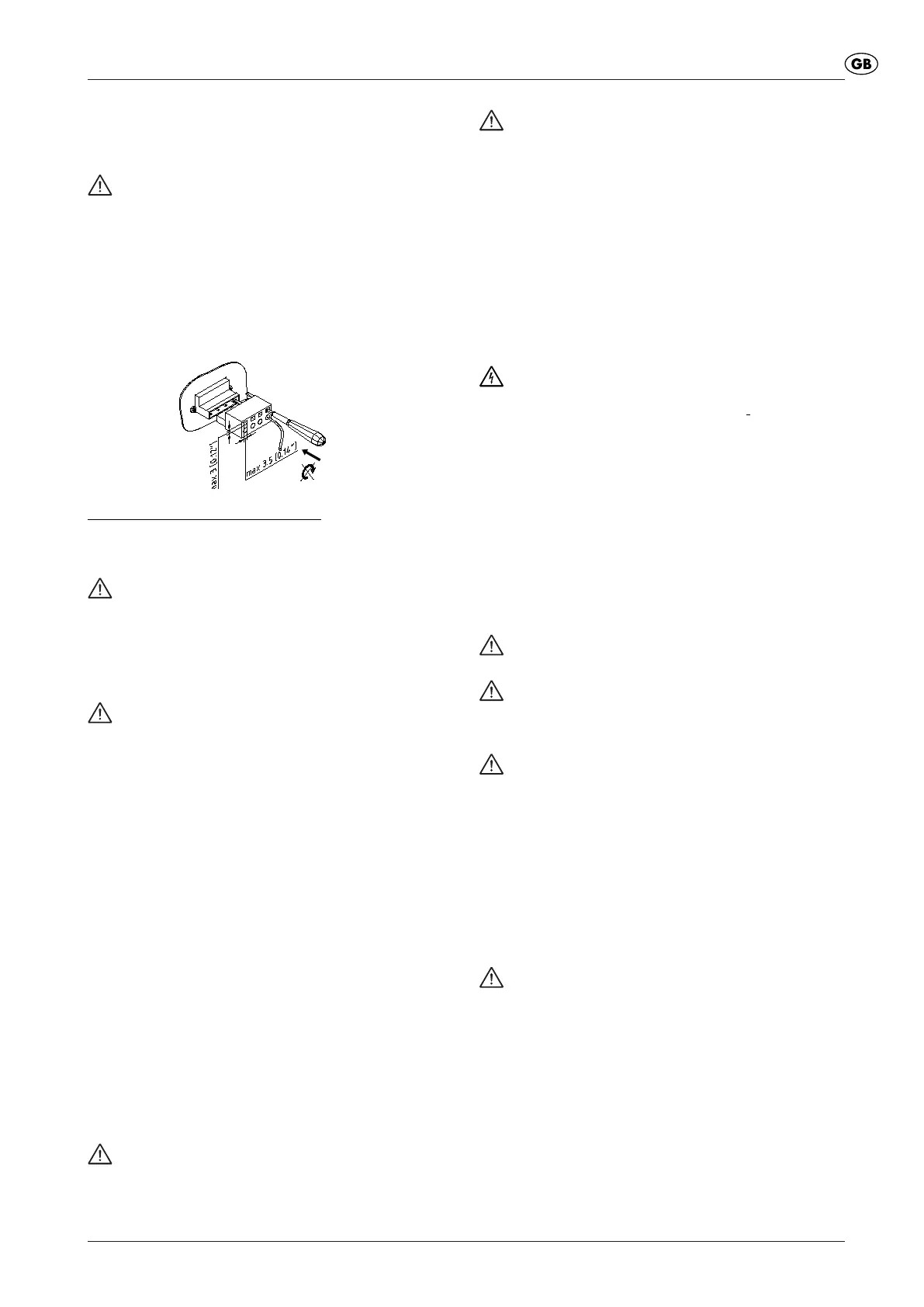
Powersupplyconnection(mains):
Both mains voltage and frequency must correspond to the nominal
values indicated on the ID plate of the cooling unit.
• Theinstallationofthepowercableisnotsubjecttoanyspecial
requirements
Attention: The cooling unit may be damaged if the
voltage is too high.
Refers to cooling units for nominal voltages 400 V/440V.
As an option, some units, differenttothestandard (400
V/440V),maybeconnectedtoadifferentmainsvoltage(For
voltagerangeseeenclosedsheet).Thefeedcablesonthe
transformer primary must be unclamped for this.
Attention! The cooling unit may be damaged due to
incorrect direction of rotation.
Before switching on the unit, check the phase sequence of the
three-phase supply in order to prevent damage to the compres-
sor.Directionofrotationmustbetotheright(clockwise).
9 Operating Conditions
• Voltage must be within ± 10 % of the value indicated.
Frequencymustbewithin±3Hzofthevalueindicated.
• Ambient temperature must be below 55 °C (for options see
supplement).
• Usetheunitsuchthatthecoolingcapacitysuitstheactualde-
mand.
• Userefrigerantasindicatedonly.
• Usegenuinesparepartsonly.
10 Putting into operation and function
10.1 General remarks
The cooling unit is provided with an electronic control system. The drawn-
in switch cabinet internal air temperature is measured by a temperature
sensor. By means of a DIP switch on the control board, different
switch cabinet temperatures as well as upper limit temperatures can
beselected(seeaccompanyingsheet).ForunitswithMulti-Controller,
selection is made from a display and control unit. Exceeding the
limit temperature generates an alarm. For units with Comfort- or
Multi-Controller, the lower temperature limit can also be monitored.
Warning!
Ambient conditions and temperature in the switch cabinet must
be in accordance with the values indicated in the supplement.
Warning! Too little heat transfer at the heat exchanger
in the external circuit (condenser).
The cooling unit may only be operated with cover, otherwise
heatdissipationatthecondenserisnotsufcient,andthe
cooling unit may be damaged.
Immediately after the switch-on of the service voltage, the
unit goes into the start-up/test mode. After that the evaporator
fan continues to run. Compressor and condenser fans run
onasrequired(thetemperatureoftheswitchingthreshold
(T
set
)has beenreached, orare switchedoff(temperature
lowerthanswitchingthreshold(T
set
)).
• Freedischargeofanycondensateproducedmustbeprovided
to ensure trouble-free operation.
11 Cleaning and Maintenance
Hazard!
Isolate the cooling unit from the mains before carrying out
any cleaning or maintenance operations.
11.1 Cleaning
The cleaning intervals depend upon the relevant operating conditions.
In particular observe the following instructions.
• Cleantheheatexchangerregularly.
• Cleantheheatexchangerusingasoftbrushorpressurizedair.
• Werecommendthatthecondensaterun-offopeningbechecked
regularly.
Proceed as follows:
1) Disconnectthecoolingunitfromthepowersupply.
2) Removeexternalcover.
3) Cleanheatexchangers
CAUTION:
Protect the electric components against leakage.
CAUTION: Damage to louvres
Do not use any pointed or sharp-edged objects. The ribs
should not be compressed or damaged during the cleaning
process.
CAUTION: Damage to electric connections on the
covering hood
If the covering hood is removed, the electric plug-in connec-
tionsontheinsidemustberemovedbyhand.Duringtting
donotforgettoplug-in!
• Ifthecoolingunitsareprovidedwithafrontltercleanthelter
mat regularly. The cleaning intervals or the intervals for replace-
mentoftheltermatmainlydependuponambientconditions(air
pollution).
• You can rinsetheltermatusingwaterheatedto 40 °C and
commercially available mild detergent. It is possible to remove
any dry dirt by knocking the mat slightly, vacuum cleaning it or
blowing it out.
CAUTION: Damage to the lter mat.
Donotwringtheltermat.Avoidtoosolidawaterjet.
•Iftheltermatisoilyorgreasy,replace.
11.2 Maintenance
The cooling circuit, as a maintenance-free, hermetically sealed closed
system,islledatthefactorywiththenecessarycoolant,checkedfor
leakages and is subjected to a functional check run. The cooling unit
is largely maintenance-free. The components around the external air
circuit require maintenance and cleaning depending upon the ambient
conditions(seeSection11.1).
After each service, the full performance capacity of the condensate
run-off should be checked.


 To Next Page
 Loading...