BG 5171 BEN / B (2017-02) PBR 260.oi 13
If the gauge is used with a
MaxiGauge™ measurement and
control unit, a corresponding
sensor cable is required
(→ 26).
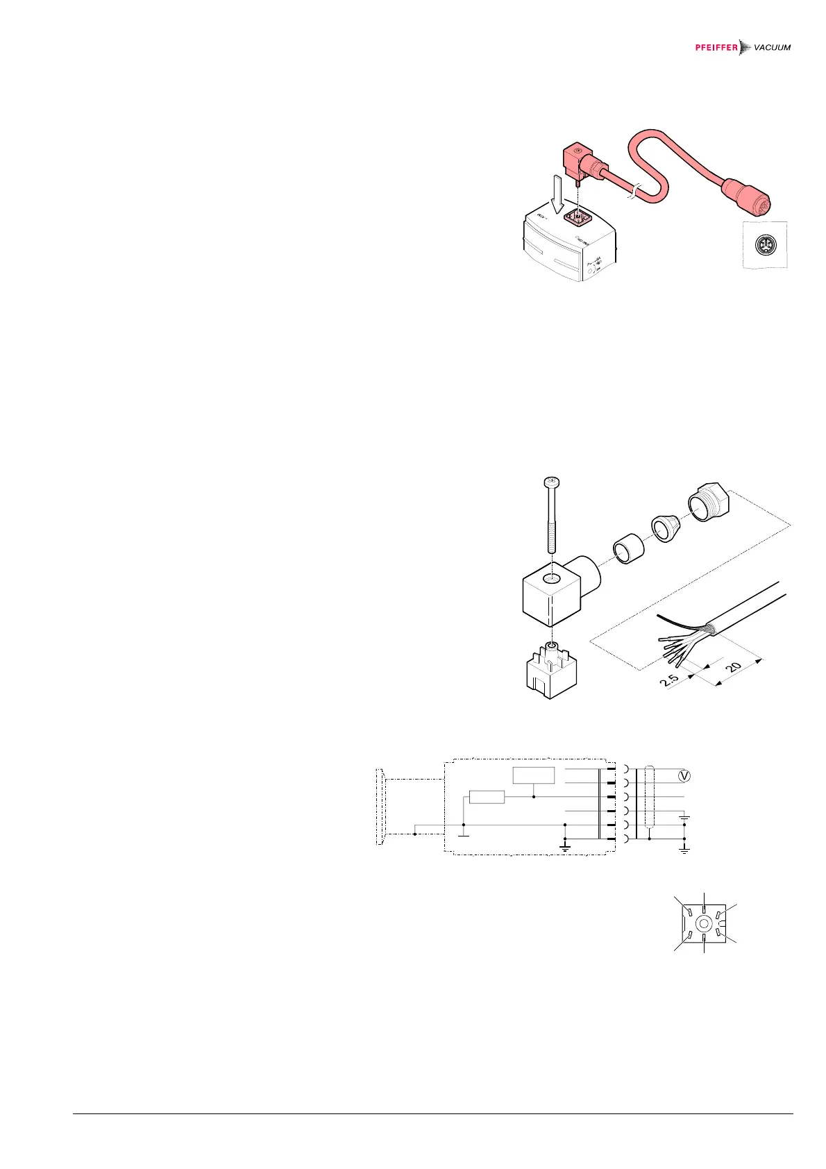
• Plug the connector into the
gauge and secure it with the
screw (tightening torque
≤ 0.2 Nm).
• Connect the other end of the
cable to the MaxiGauge™
and secure it.
The gauge can also be used with other evaluation units. In such a case, an indi-
vidual sensor cable can be made (preconfigured cables → 26).
Due to the high current consumption, only differential measurement between the
signal output (pin 2) and signal common (pin 3) is admissible.
Prepare the connector
(ordering number
→ 26).
Prepare the cable.
Solder the sensor cable according to the diagram.
–
+
–
+
Degas
Degas
17.2 k
2
3
4
1
5
6
Figure 1: Electrical connection
Pin 1 a) degas
b) identification
(U ≤ 4.25 V)
Pin 2 signal output
(measuring signal)
Pin 3 signal common GND
Pin 4 supply
Pin 5 supply common GND
Pin 6 shielding
2
5
3
1
6
4
Connector, soldering side
3.2 Power Connection
3.2.1 Use With MaxiGauge™
3.2.2 Use With Other
Evaluation Units
Procedure
 Loading...