BG 5171 BEN / B (2017-02) PBR 260.oi 15
4 Operation
When the voltage is supplied, the measuring signal is available between pins 2 and
3. Over the whole measurement range, the measuring signal is output as a
logarithm of the pressure (relationship between measuring signal and pressure
→ Appendix B).
Allow for a stabilizing time of approx. 10 min. Once the gauge has been switched
on, permanently leave it on irrespective of the pressure.
The PBR 260 consists of two separate measuring systems (hot cathode Bayard
Alpert (BA) and Pirani).
The BA measuring system uses an electrode system according to Bayard Alpert
which is designed for a low x-ray limit.
The measuring principle of this system is based on gas ionization. Electrons
emitted by the hot cathode (F) ionize a number of molecules proportional to the
pressure in the measuring chamber. The ion collector (IC) collects the thus
generated ion current I
+
and feeds it to the electrometer amplifier of the measure-
ment instrument. The ion current is dependent upon the emission current I
e
, the
gas type, and the gas pressure p according to the following relationship:
I
+
= I
e
× p × C
Factor C represents the sensitivity of the gauge. It is generally specified for N
2
.
The lower measurement limit is 5×10
-10
hPa (metal sealed).
For the whole range of 5x10
-10
hPa ... 10
-2
hPa to be sensibly covered, a low
emission current is used in the high pressure range (fine vacuum) and a high
emission current is used in the low pressure range (high vacuum). The switching of
the emission current takes place at decreasing pressure at approx. 7.2×10
-6
hPa,
at increasing pressure at approx. 3.2×10
-5
hPa. At the switching threshold the
PBR 260 can temporarily (< 2 s) deviate from the specified accuracy.
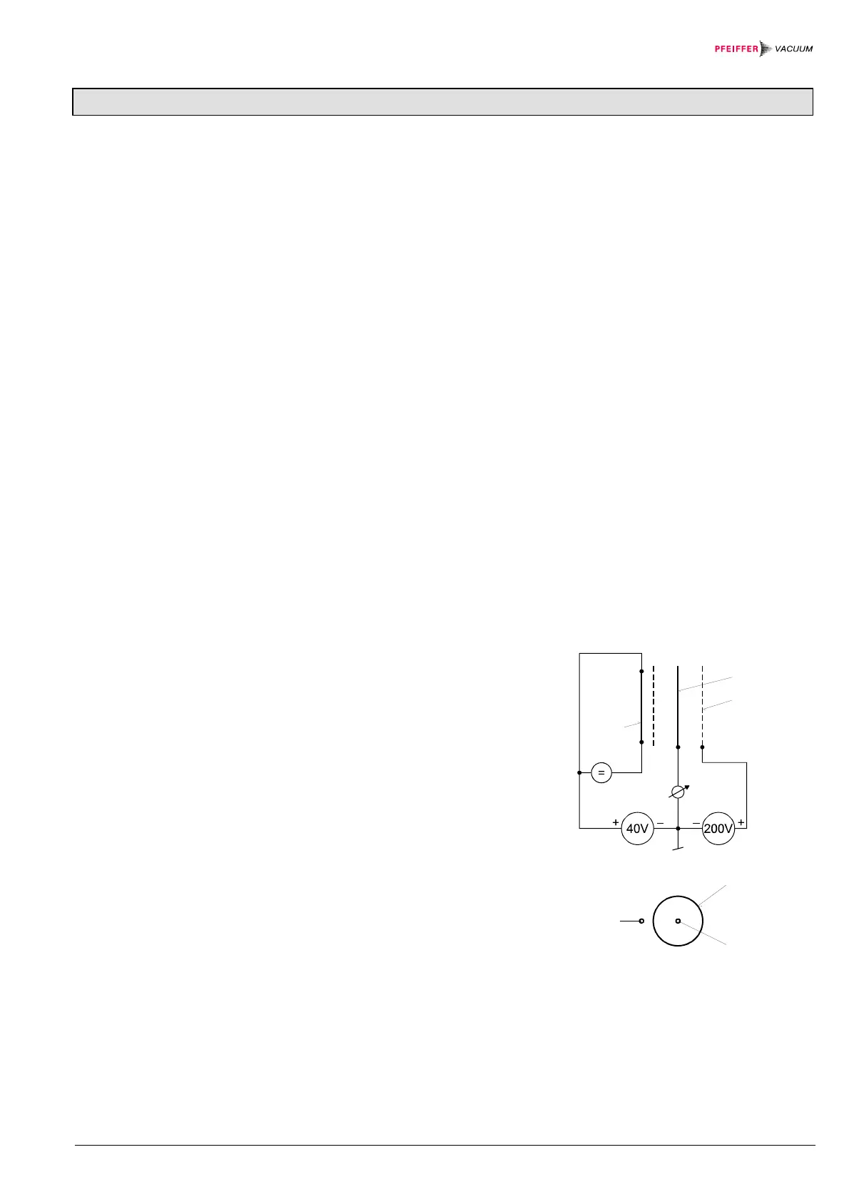
Fig. 1
Diagram of the BA measuring system
F hot cathode (filament)
IC ion collector
EC electron collector (grid)
EC
IC
F
EC
IC
F
(Degas 2.5V) (Degas 250V)
4.1 Measuring Principle,
Measuring Behavior
Bayard Alpert
 Loading...