23
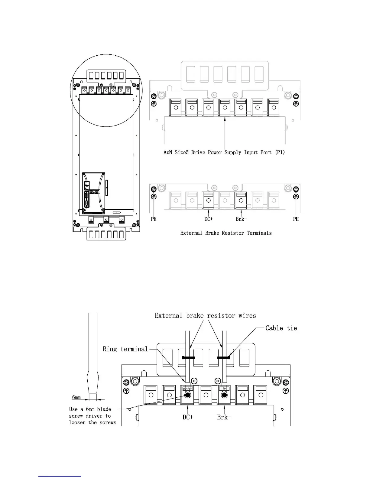
top of the drive. Refer to the following figures for exact locations and terminal Assignment.
Step 4: Insert Wires into Corresponding Terminals
Use a 6mm blade screw driver to loosen the screws on DC+ and Brk- Terminals which are in the
drive’s Power Supply Input Port (P1). Insert the two wires of the external brake resistor separately
into these two terminals. Then tight the screws.
Step 5:Wire Fixing
Use a cable tie to fix the wires on the cable support of AxN Size5 drive.