53
4.6 U1/U2 —— User Connectors
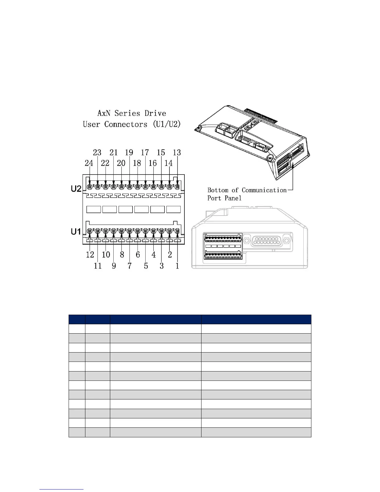
Port Location
AxN Series Drive’s User Connectors (Male Plug, 2 × 12 pin) are on the left bottom of the
Communication Port Panel. Refer to the following figure for exact location.
Pin Assignment
User Connector U1
Differential analog input
Differential analog input
Programmable analog output
Programmable digital input
6.6 kΩ to ground, 20-30 V
Programmable digital input
6.6 kΩ to ground, 20-30 V
Programmable digital input
6.6 kΩ to ground, 20-30 V
Programmable digital input
6.6 kΩ to ground, 20-30 V
Programmable digital output
PNP open collector, 24 V, 100mA max
Programmable digital output
PNP open collector, 24 V, 100mA max
Auxiliary supply of control circuits
22 ~ 30Vdc to Pin 12 (0V), 500mA
Auxiliary supply negative