12
FREEZER COMPONENTS
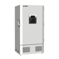
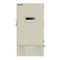
1. Control panel: The chamber temperature and other alarms/functions can be set using the keys on the
control panel. The operational status can be checked on the temperature display and indicators [page
13].
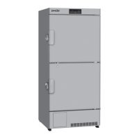
2. Outer door latch: Always lock the outer door latch when the outer door is closed.
3. Inner door: This prevents cold air from escaping when the outer door is opened. Always be sure to
close the inner door securely before closing the outer door. The inner door can be removed for cleaning
or defrosting [page 43].
4. Inner door latch: Always lock the inner door latch when the inner door is closed.
5. Air intake vent: This is an air intake vent for circulating the air in the chamber. Do not block this vent.
Blocking this vent may cause unstable chamber temperature.
Do not insert fingers or other objects into this vent.
6. Levelling foot <bottom>: These are screw bolts used to install and fix the unit. Adjust the height of
the levelling feet by turning the screw bolts until the two front casters are away from the floor [page 15].
7. Space for temperature recorder: A temperature recorder (optional) can be mounted here so that the
chamber temperature can be recorded automatically [page 52].
Contact our sales representative or agent for the installation.
8. Access port <rear and bottom>: These ports are used to pass the sensor or cable of measuring
equipment, the sensor of a temperature recorder (optional), or the nozzle of a back-up cooling kit
(optional) to the chamber.
Replace the insulation and the rubber caps when the access port is not in use. Improper replacement
may cause an increase in chamber temperature or condensation around the access port.
9. Air release port: Used to re-open the outer door immediately after closing it [page 38].
10. Remote alarm terminal: A remote alarm device (separately available) can be connected to this
terminal. The remote alarm relays the alarm to an operator in a remote location if the unit is un attended.
Refer to page 38 for details.
Contact our sales representative or agent to arrange the installation.
11. Power switch: This is the power switch of the unit.
12. Battery switch: This is an ON-OFF switch for the battery for the power-failure alarm. Always turn
this switch on when the unit is operating to ensure that the power-failure alarm is working. Turn this
switch off when the unit is not used for a long period in order to protect the battery.
13. Fixture: Use the fixtures and secure the unit to a wall with a strong rope or chain [page 15].