Service Modes, Error Codes, and Fault Finding
EN 19LC7.2E LB 5.
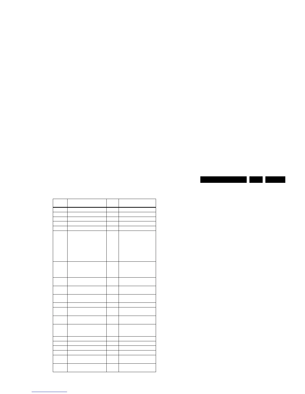
Table 5-2 Error code overview
Notes
1. Some of the error codes reported are depending on the
option code configurations.
2. This error means: no I2C device is responding to the
particular I2C bus. Possible causes: SCL/SDA shorted to
GND, SCL shorted to SDA, or SCL/SDA open (at uP pin).
The internal bus of the Trident platform should not cause
the entire system to halt as such an error can be reported.
5.4.4 How to Clear the Error Buffer
The error code buffer is cleared in the following cases:
• By using the CLEAR command in the SAM menu:
– To enter SAM, press the following key sequence on the
remote control transmitter: “062596” directly followed
by the OSD/i+ button (do not allow the display to time
out between entries while keying the sequence).
– Make sure the menu item CLEAR is selected. Use the
MENU UP/DOWN buttons, if necessary.
– Press the MENU RIGHT button to clear the error
buffer. The text on the right side of the “CLEAR” line will
change from “CLEAR?” to “CLEARED”
• If the contents of the error buffer have not changed for 50
hours, the error buffer resets automatically.
Note: If you exit SAM by disconnecting the mains from the
television set, the error buffer is not reset.
5.5 The Blinking LED Procedure
5.5.1 Introduction
The software is capable of identifying different kinds of errors.
Because it is possible that more than one error can occur over
time, an error buffer is available, which is capable of storing the
last five errors that occurred. This is useful if the OSD is not
working properly.
Errors can also be displayed by the blinking LED procedure.
The method is to repeatedly let the front LED pulse with as
many pulses as the error code number, followed by a period of
1.5 seconds in which the LED is “off”. Then this sequence is
repeated.
Example (1): error code 4 will result in four times the sequence
LED “on” for 0.25 seconds / LED “off” for 0.25 seconds. After
this sequence, the LED will be “off” for 1.5 seconds. Any RC5
command terminates the sequence. Error code LED blinking is
in red colour.
Example (2): the content of the error buffer is “12 9 6 0 0”
After entering SDM, the following occurs:
• 1 long blink of 5 seconds to start the sequence,
• 12 short blinks followed by a pause of 1.5 seconds,
• 9 short blinks followed by a pause of 1.5 seconds,
• 6 short blinks followed by a pause of 1.5 seconds,
• 1 long blink of 1.5 seconds to finish the sequence,
• The sequence starts again with 12 short blinks.
5.5.2 Displaying the Entire Error Buffer
Additionally, the entire error buffer is displayed when Service
Mode “SDM” is entered. In case the TV set is in protection or
Stand-by: The blinking LED procedure sequence (as in SDM-
mode in normal operation) must be triggered by the following
RC sequence: “MUTE” “062500” “OK”.
In order to avoid confusion with RC5 signal reception blinking,
this blinking procedure is terminated when a RC5 command is
received.
To erase the error buffer, the RC command “MUTE” “062599
“OK” can be used.
Error
code
1)
Description Item nr. Remarks
0 No error.
1 DC Protection of speakers.
2 +12V protection error. 12V missing or “low”.
3 Reserved.
4 General I2C error. note 2
5 Trident Video Processor
communication error.
7202 When Trident IC is
defective, error 10 and 14
might also be reported.
Trident communicates via
parallel bus, not via the I2C
bus. The I2C bus of Trident
is only used in ComPair
mode.
6 I2C error while communicating
with the NVM.
7315 The TV will not start-up due
to critical data not available
from the NVM, but the LED
will blink the error code.
7 I2C error while communicating
with the Tuner.
1101
8 I2C error while communicating
with the IF Demodulator.
7113
9 I2C error communicating with
the Sound Processor.
7411
10 SDRAM defective. 7204
11 I2C error while communicating
with the HDMI IC.
7817
12 I2C error while communicating
with the MOJO PNX8314.
7G00 if applicable
13 DVB HW communication
error.
7F01,
7K00,
7G00
if applicable
14 SDRAM defective. 7205
15 Reserved.
16 Reserved.
17 Reserved.
18 I2C error while communicating
with the iBoard processor.
if applicable
19 I2C error while communication
with 1080p bolt-on module.
if applicable