Circuit Descriptions, Abbreviation List, and IC Data Sheets
EN 87LC7.2E LB 9.
9.11 IC Data Sheets
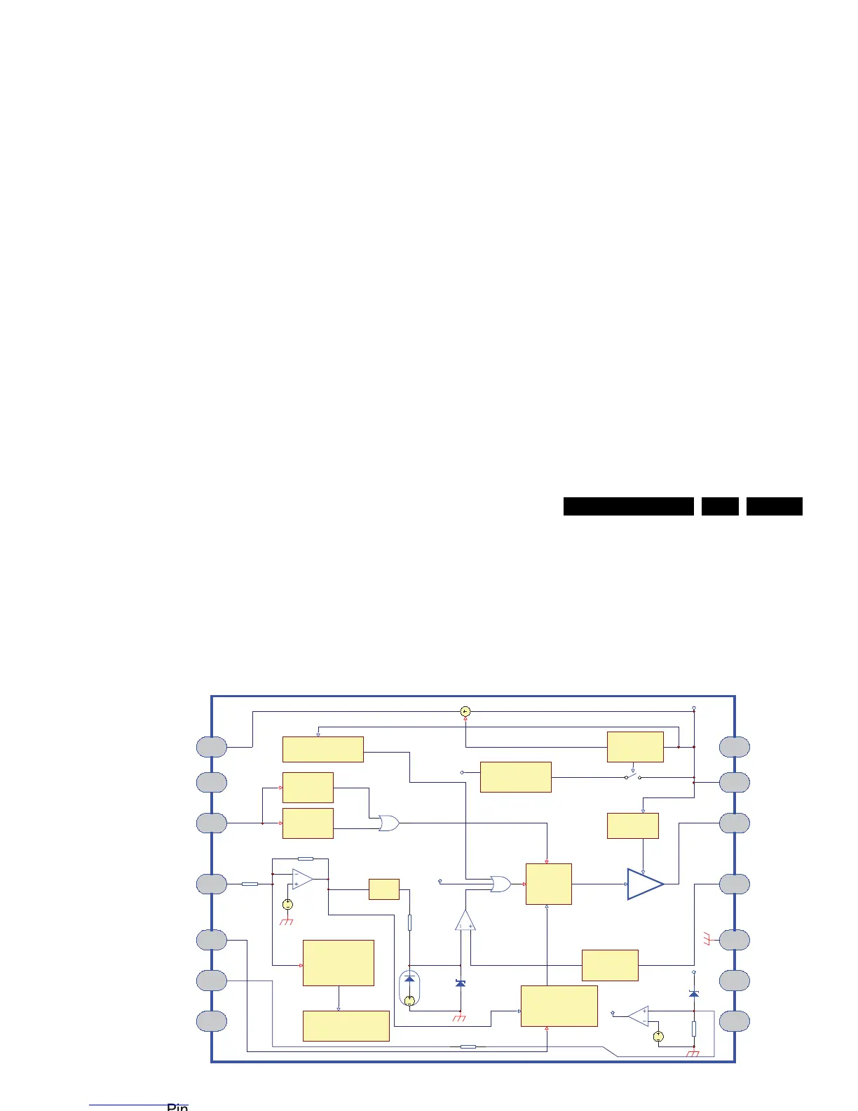
This section shows the internal block diagrams and pin layouts
of ICs that are drawn as “black boxes” in the electrical diagrams
(with the exception of “memory” and “logic” ICs).
9.11.1 Diagram A1, Type TY72011AP2 (IC U130), PWM Controller
Figure 9-12 Internal block diagram and pin configuration
1
2
3
4
5
6
78
9
10
11
12
13
14
HV
Demag
FB
Ct
OVP
Isense
GND
Vcc
Drive
nc
nc
nc
ncnc
UVLOh = 15V
UVLOl = 7.2V
DEMAG ?
2.5V
Over Current
Protection (OCP)
V(-) < 1.5V
More than 128ms?
Toff = f (Verr)
Max Toff = f (Ct)
VCO Feedback
Startup
--> protection circuitry
Internal Vcc
1
3
4
5 10
11
12
14
Internal regulator
HV
Demag
FB
Ct Gnd
Isense
Vcc
Verr max = 3V
Verr min = 10mV
DRV
Driver
Last pulse of
demag after 4µs
1/3
1V
Rf
Ri
Current comparator
Flip-Flop
250mV clamp
250mV - 1V max setpoint
Clock
R
D
Q
Verr
Internal Clamp
Over Voltage
Protection (Vcc > 41V?)
200ns L.E.B
2
NC
NC
OVP
6
7
4x10V zener
Vcc pin13
Vcc pin8
500
OVP
OVP
60mV
20k
13
9
8
NC
NC
Block Diagram
Pin Configuration
H_17170_034.eps
250507