Circuit Descriptions, Abbreviation List, and IC Data Sheets
EN 79LC7.2E LB 9.
9. Circuit Descriptions, Abbreviation List, and IC Data Sheets
Index of this chapter:
9.1 Introduction
9.2 Main Supply
9.3 DC/DC converters
9.4 Front-End
9.5 DVB-T Signal Processing
9.6 Video Processing
9.7 Memory addressing
9.8 Audio Processing
9.9 HDMI
9.10 Abbreviation List
9.11 IC Data Sheets
Notes:
•Only new circuits (circuits that are not published recently)
are described.
• Figures can deviate slightly from the actual situation, due
to different set executions.
• For a good understanding of the following circuit
descriptions, please use the Wiring, Block (chapter 6) and
Circuit Diagrams (chapter 7). Where necessary, you will
find a separate drawing for clarification.
9.1 Introduction
The LC7.x (development name “LC07”) is a new global chassis
for the year 2007 (LC7.1 is the analogue range, LC7.2 is the
digital range). It is the successor of the LC4.x chassis. The
LC7.xx LB covers a screen size of 19 to 23 inch with a new
styling called “BELT”. Some key components are:
• Audio: Sound processing is performed by a multi-standard
sound processor MSP4450 (item 7411)
• Video: Video processing is performed by the Trident video
processor SVP CV32-LF (item 7202).
For analogue reception, a standard IF demodulator is used,
whereas digital input signals (DVB-T) are processed through a
COFDM channel decoder together with an MPEG decoder
(integrated on the SSB). A so-called “Reneas” microprocessor
performs the control functionality.
9.1.1 SSB Cell Layout
Description of the functional blocks (top side):
• In the middle, there is the Trident video processor.
• Above it, there is the Reneas micro processor.
• At the right hand top, there is the audio class D amplifier.
• The left part of the SSB contains the digital reception
circuit. In the LC4.x, this was a separate module, here it is
integrated on the SSB (same MOJO chipset).
• Between the digital reception part and the Trident part,
there is the DC/DC conversion circuit.
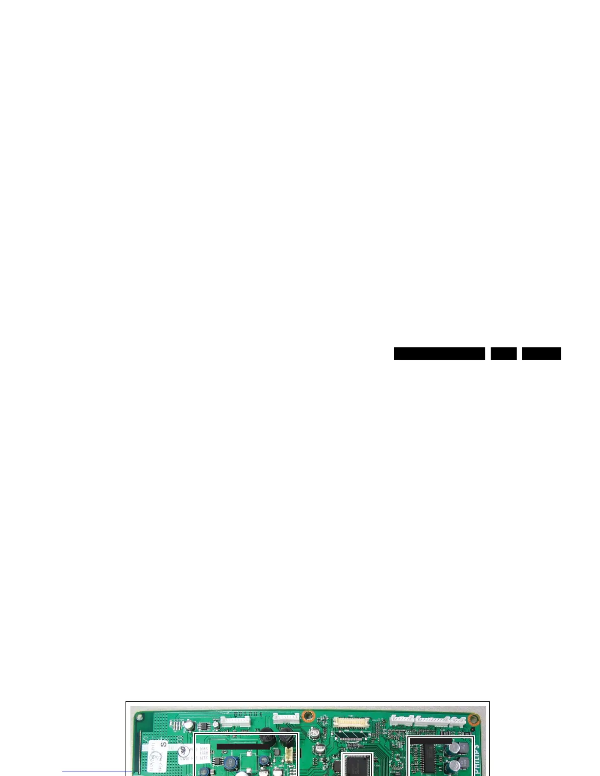
Figure 9-1 SSB top view
Description of the functional blocks (bottom side):
• The “Flash Mem” chip contains the software of the TV.
• The “Micronas” is the audio demodulator/processor.
• The two SDRAM’s are used for the video processing.
• The right part of the SSB contains the digital reception
circuit. This side contains the channel decoder.
• There are two connectors for ComPair:
– One on the other side of the tuner for I2C
communication with the Reneas micro processor.
– The other one at the digital reception part, for UART
communication with the MOJO.
G_16860_048.eps
310107
DC-DC CONVERSION
TRIDENT
VIDEO
PROC.
RENEAS
uP
AUDIO CLASS D
COMMON INTERFACE
HYBRID TUNER
PCMCIA
CONTROLLER
MOJO
SDRAM
FLASH
MEM
IF DEM
HDMI
VIF SAW
SIF SAW