Circuit Descriptions, Abbreviation List, and IC Data Sheets
EN 80 LC7.2E LB9.
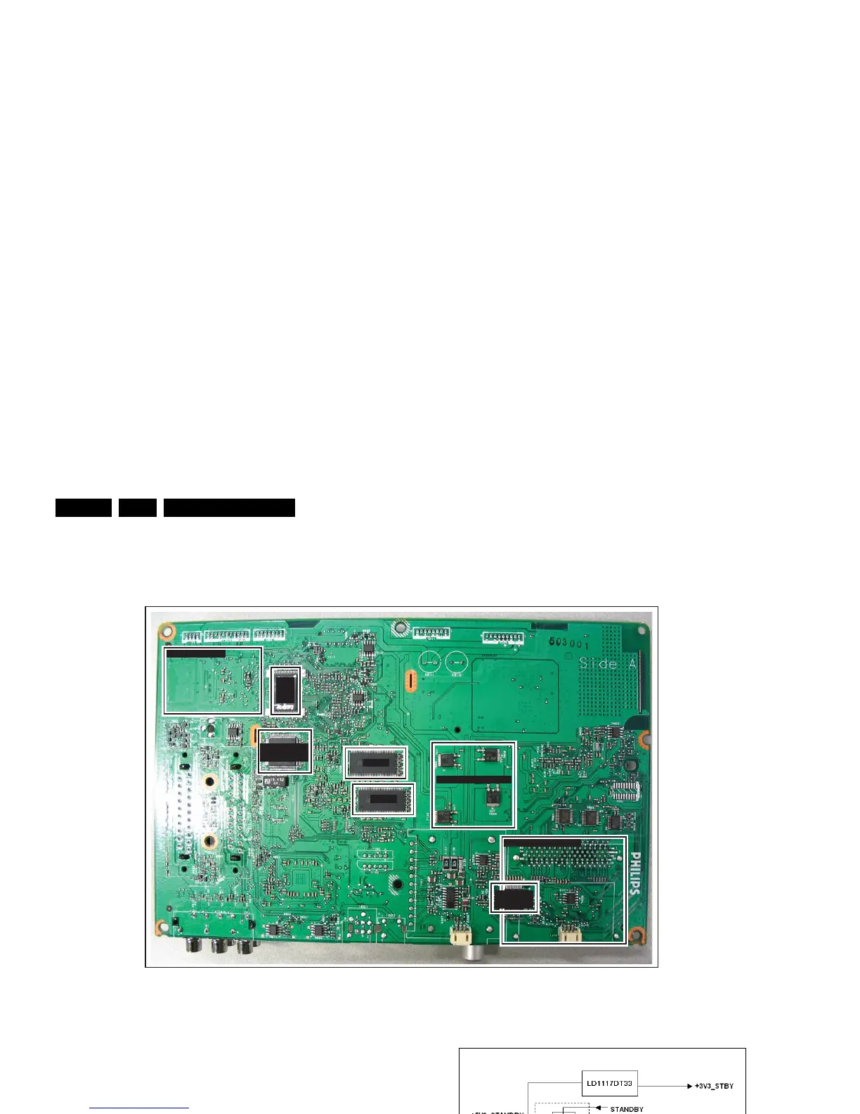
Figure 9-2 SSB bottom view
9.2 Main Supply
The Main Power Supply Unit (PSU) in this chassis is a buy-in
“Jabil” supply unit and is a black-box for Service. When
defective, a new panel must be ordered and the defective panel
must be returned for repair, unless the main fuse of the unit is
broken. Always replace the fuse with one of the correct
specifications! This part is commonly available in the regular
market.
The Main Power Supply Unit delivers the following voltages to
the chassis:
• +12 V to SSB
• +12 V and -12 V to Audio Supply
• +5.2 V Standby voltage
• +3.3 V LVDS supply.
9.3 DC/DC converters
A switch generates the +5.2 V (+5V_SW) from the +5.2 V
(+5V_STANDBY) supply voltage. For LCD sets, this switch is
mounted on-board the SSB. This results in the +5V_STANDBY
voltage(s), coming from the Power Supply Unit, is (are) used as
input for the on-board DC/DC converters.
They deliver the following voltages to the board:
• +3.3 V (+3V3_STBY)
• +5.2 V (+5V_SW) (only for LCD sets)
• +1.8 V (+1V8S_SW)
• +34 V (+VTUN)
• +3.3 V (+3V3_SW)
• +3.3 V (+3V3_MOJO)
• +1.2 V (+1V2_MOJO)
An overview can be found in figure “DC-DC converter block
diagram”.
Figure 9-3 DC-DC converter block diagram
The +5 V switch, needed for the switch voltages, is for LCD
sets physically mounted on the SSB.
G_16860_049.eps
310107
DC-DC CONVERSION
AUDIO CLASS D
COMMON INTERFACE
FLASH
MEM
SDRAM
SDRAM
CHANNEL
DECODER
MICRONAS
AUDIO PROC.
G_16860_063.eps
270707
(n.a. for LC7.xH)
(n.a. for LC7.xH)
(n.a. for LC7.xH)