Alignments
EN 76 LC7.2E LB8.
• When finished return to the SAM root menu and press
STANDBY on the RC to store the aligned values to the
NVM.
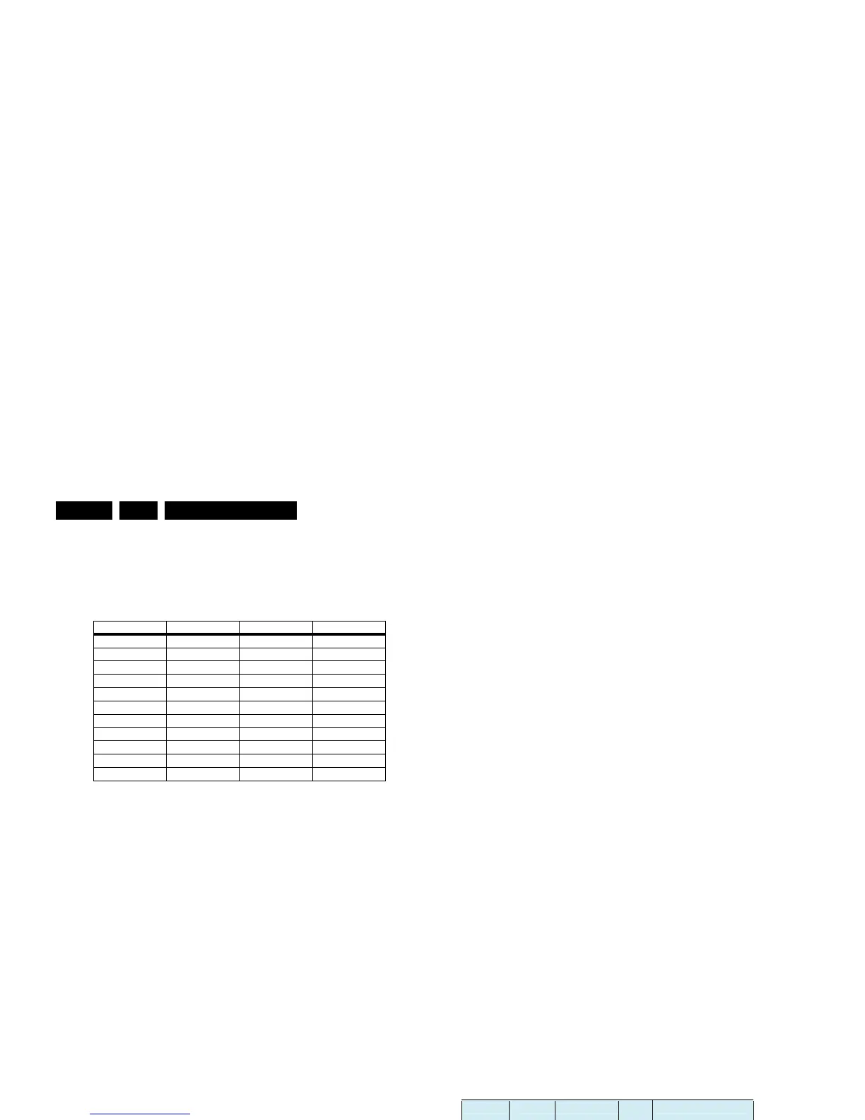
Table 8-2 Tint settings
Black Level Offset Alignment
• Activate SAM.
• Select “RGB Align.” -> “BlackL Offset” and choose a colour.
• Set all “BlackL Offset” values to “0”.
• When finished return to the SAM root menu and press
STANDBY on the RC to store the aligned values to the
NVM.
Note: For models with “Pixel Plus”, the “Black Offset” (black
level offset) should NOT be changed in SAM. These offset
values of RGB should be set to “0”, and should NOT be
adjusted. Any adjustment of these values will affect the low
light white balance.
ADC YPbPr Gray Scale Alignment
When the grey scale is not correct, use this alignment:
• Activate SAM.
• Select “NVM Editor”.
• Enter address “26(dec)” (ADR).
• Set value (VAL) to “197(dec) ± 25”.
• Store (STORE) the value.
8.4 Option Settings
8.4.1 Introduction
The microprocessor communicates with a large number of I
2
C
ICs in the set. To ensure good communication and to make
digital diagnosis possible, the microprocessor has to know
which ICs to address. The presence/absence of these specific
ICs (or functions) is made known by the option codes.
Notes:
• After changing the option(s), save them with the STORE
command.
• The new option setting becomes active after the TV is
switched “off” and “on” again with the mains switch (the
EAROM is then read again).
8.4.2 How To Set Option Codes
When the NVM is replaced, all options will require resetting. To
be certain that the factory settings are reproduced exactly, you
must set all option numbers. You can find the correct option
numbers in table “Option Codes OP1...OP7“below.
How to Change Options Codes
An option code (or “option byte”) represents eight different
options (bits). When you change these numbers directly, you
can set all options very quickly. All options are controlled via
seven option bytes (OP1... OP7).
Activate SAM and select “Options”. Now you can select the
option byte (OP1.. OP7) with the CURSOR UP/ DOWN keys,
and enter the new 3 digit (decimal) value. For the correct
factory default settings, see the next table “Option codes
OP1...OP7“. For more detailed information, see the second
table “Option codes at bit level“. If an option is set (value “1”), it
represents a certain decimal value.
When all the correct options (bits) are set, the sum of the
decimal values of each Option Byte (OP) will give the option
code.
Figure 8-1 Option codes OP1...OP7
Alignment 19" 20" 23"
COOL_RED 248 246 248
COOL_GREEN 253 256 253
COOL_BLUE 256 254 256
NORMAL_RED 256 250 256
NORMAL_GREEN 256 256 256
NORMAL_BLUE 245 240 245
WARM_RED 256 256 256
WARM_GREEN 242 243 242
WARM_BLUE 211 203 211
H_17170_033.eps
010807
Sets 12NC Sets Type LCD Panel Type Option Byte (Dec)
Group 1 Group 2
LC07_EU_DTV_LCD_UK (/05)
1 2 3 4 5 6 7
8670 000 29842 19PFL5522D/05
8670 000 30539 19PFL5602D/05
CMO: M190A1-L02 105 07
LPL: LC201V02-SDB1 103
8670 000 29822 20PFL5522D/05
AUO: A201SN02 V5 104
LPL: LC201V02-SDB1 103
8670 000 30667 20HF5335D/05
AUO: A201SN02 V5 104
06
8670 000 29743 23PFL5522D/05 AUO: T230XW01_V3 106
19
07
10 223 09 02
223 09 02
01
LC07_EU_DTV Pan Europe (/12)
8670 000 29841 19PFL5522D/12
8670 000 30541 19PFL5602D/12
CMO: M190A1-L02 105 07
LPL: LC201V02-SDB1 103
8670 000 29839 20PFL5522D/12
AUO: A201SN02 V5 104
LPL: LC201V02-SDB1 103
8670 000 30147 20HF5335D/12
AUO: A201SN02 V5 104
06
8670 000 29744 23PFL5522D/12 AUO: T230XW01_V3 106
13
07
10 01
LCD Panel
Code (Dec)