Do you have a question about the Philips 19PFL5522D and is the answer not in the manual?
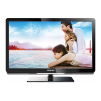
Detailed technical parameters including display, resolution, contrast, response time, viewing angles, power, and dimensions.
Visual guide and description of all side and rear I/O ports and connectors for video, audio, and control signals.
Identifies major internal components like Main Supply Unit, Top Control Panel, and LCD Interface Panel.
Essential safety regulations for repair, including isolation transformers, component substitution, and checking insulation.
Critical warnings and cautions regarding voltage, humidity, foreign substances, and handling the LCD Module.
Guidelines for system assemblers on preventing physical stress, overheat, dust, and ensuring correct power sequence.
Describes methods for positioning the TV for easy servicing, using buffers, foam bars, or stands.
Step-by-step instructions for removing components like the rear cover, control panel, and I/O modules.
Details the use of foam bars for supporting displays during servicing to prevent damage.
Explains the identification and measurement of test points, including the use of test patterns.
Details on Service Default Mode (SDM), Alignment Mode (SAM), Customer Service Mode (CSM), and ComPair.
Overview of error codes and how they are displayed via OSD or blinking LEDs.
General advice on troubleshooting, checking options, NVM editor, and loading default values.
Illustrates the wiring connections for the main supply, control panel, side I/O, and LCD panel.
Shows the signal flow for video processing from various inputs to the LCD panel.
Illustrates the audio signal path from tuners and inputs to speakers and headphones.
Details the control and clock signals distributed throughout the system and between key ICs.
Provides a detailed layout of test points on the Small Signal Board (SSB) bottom side for measurement.
Shows the interconnections and communication paths of ICs using the I2C bus.
Illustrates the distribution of various power supply lines across different modules and boards.
Specifies the required conditions for performing electrical adjustments, including power supply and test probe requirements.
Details software-based alignments like Tuner RF AGC and RGB alignment for white tone and grey scale.
Explains how to set option codes for the microprocessor to recognize specific ICs or functions.
Describes the Main Power Supply Unit (PSU) as a buy-in black-box unit for service.
Discusses tuner diversity and the function of the TD1316AF hybrid tuner for analogue and digital signals.
Explains the DVB-T signal path involving the MOJO MPEG decoder and COFDM channel decoder.
Details the features of the Trident SVP CX32 video processor for video processing tasks.
Explains audio decoding performed by the MSP4450P, including ASD and ASS functionalities.
Provides an introduction to the HDMI interface and its implementation using the Sil 9025 receiver IC.
Lists and defines common abbreviations used throughout the manual, such as CCFL, FFC, I2C, and PSU.
Shows internal block diagrams and pin layouts for key ICs used in the circuit.
| brightness | 300 cd/m² |
|---|---|
| contrast ratio | 1000:1 |
| response time | 5 ms |
| viewing angle | 160 / 160 degree |
| diagonal screen size | 19 inch / 48 cm |
| panel resolution | 1440 x 900p |
| output power | 2 x 5W |
|---|---|
| equalizer | 7-bands |
| built-in speakers | 2 |
| ambient temperature | 5 °C to 40 °C |
|---|---|
| mains power | 220 - 240V, 50/60Hz |
| power consumption | < 55 W |
| standby power consumption | < 1 W |
| set dimensions | 478 x 370 x 85 mm |
|---|---|
| set dimensions with stand | 478 x 417 x 193 mm |
| product weight | 6.3 kg |
| product weight with stand | 7.8 kg |
| box dimensions | 557 x 535 x 195 mm |
| VESA wall mount compatible | 100 x 100 mm |