Circuit Descriptions
EN 35LC9.3L LA 7.
2010-Mar-26
7.8 Ambilight
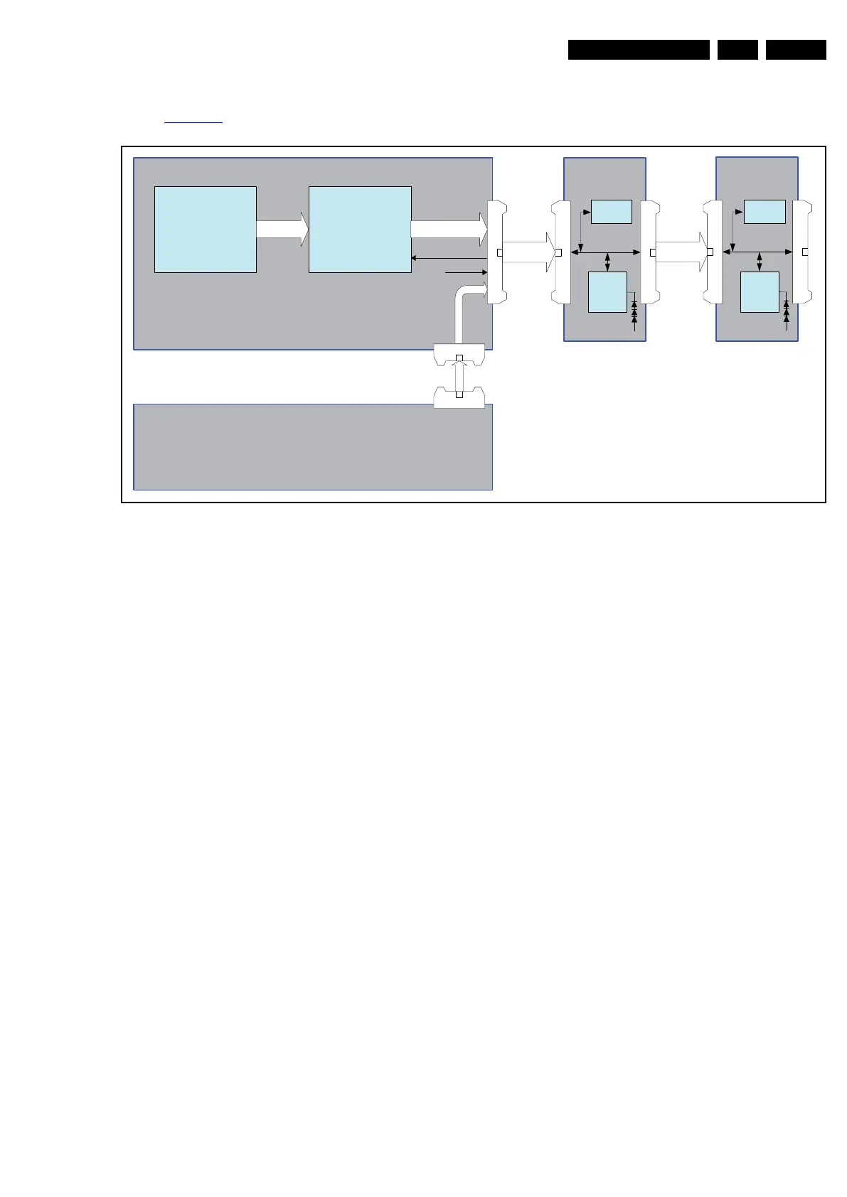
Refer to Figure 7-10 for the Ambilight architecture.
Figure 7-10 Ambilight architecture
The MTK5392 outputs through an I
2
C bus. The data is then
captured by the LPC2103 microprocessor which converts the
RGB input data (I
2
C) into RGB output through an SPI bus,
which is further transmitted to the Ambilight LED board via an
SPI interface (SPI + extra signals).
18970_208_100325.eps
100325
MTK5392
μP
LPC2103
I
2
C AMBI-S PI
+24V
+ 3V 3
1M72
4P 2.0mm
1M59
1M09
4P 2.0mm
4p
1M83
25p FFC
Ambilight Board 1
Temp s ensor
MTK SSB
P S U
1M84
25p FFC
LED
driver
TLC5946
EEPROM
1M83
Ambilight Board 2
1M84
LED
driver
TLC5946
EEPROM