when the PU arm is raised at the END OF A PLAYED PLATE, THAT ONE GETS BACK
WHEN THE NEEDLE TURNS THE PLATE.
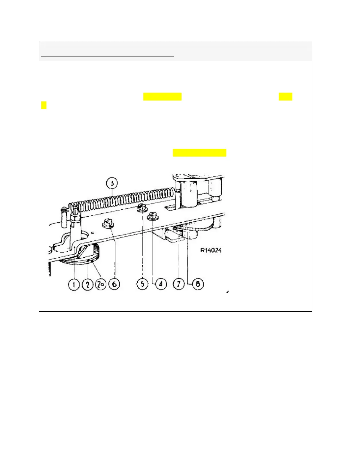
The space between the ‘B’ lift plate (1, and the lifting plate (2) is more than 0.3 mm.) Place the device
in the "rest position" (toothless part of the command dial opposite the main shaft) and place the P U
arm on the support on the start switch. Remove spring (3)[fig 8 81] and unscrew the screws (4), (5) and
(6) FIG 8 .C a few turns, press the bracket (7) against the roller (8) and slide the lift plate [1] in the
opposite direction so that there is a space of 0.3 mm between the angle bent part of the lift plate and
the slanted part of the lift disc [2]. Then tighten the screws [4] and [5] again.
R14024
LONG PLATE ‘B’ [lift plate /CHANGE PLATE..fig 8 .B [CALLED ITEM 1 HERE] HAS NO P/N...it also has the
leaf ‘A’ involved w the TASTER w no P/N...
IX THE DEVICE DOES NOT STOP AFTER IT IS
PLACED IN THE "STOP".
1. The pivot point of the stop bracket
51
 Loading...