Mechanical Instructions
EN 6 VAD80414.
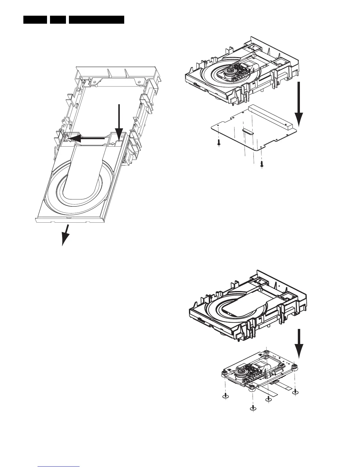
4.4 Tray
– Remove encasing as as described in 4.3
– Disengage the two holders that fix the tray [1], see figure 4-
2, and pull out the tray [2]
Figure 4-2 Remove Tray
4.5 Printed Board
Note: After exchanging the PWB (or the DVD-M) the complete
drive has to be adjusted! Run command 931 of DSW
(AdjustLaserControl). Refer to chapter 8 for adjustment
instructions!
– Remove encasing as described in 4.3
– Disconnect the 2 flex foils from the PWB connectors and
the OPU flex
– Remove the 2 screws that hold the PWB, see figure 4-3
– Remove the PCB
– Remove the yellow plate if needed by releasing the 2 snap
hooks
Figure 4-3 Remove PWB
4.6 DVD-M
Caution: Never try to align or repair the DVD-Module itself!
Only the factory can do this properly. Service engineers are
only allowed to exchange the sledge motor assy.
After Exchanging the DVD-M (or the PWB) the complete drive
has to be adjusted! Run command 931 of DSW
(AdjustLaserControl). Refer to chapter 8 for adjustment
instructions!
– Remove PCB as described in 4.5
– Remove the four screws [1], see figure 4-4.
– Now you can remove the DVDM
Figure 4-4 Remove DVDM
1
1
2
1
2
1
2
1
1
1
1