Mechanical Instructions
EN 7VAD8041 4.
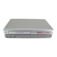
4.7 Sledge Motor Assembly
Caution: Never try to align or repair the DVD-Module itself!
Only the factory can do this properly. Service engineers are
only allowed to exchange the sledge motor assy.
– Eject the tray.
– Remove the 2 screws that hold the sledge motor, see
figure 4-5
– Remove the sledge motor
Figure 4-5 Remove Sledge Motor Assy
4.8 Re-assembly
To re-assemble the module, do all processes in reverse order.
Take care of the following:
• Complete module: Place all wires/cables in their original
position
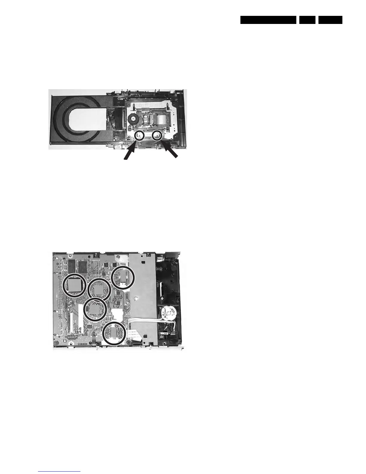
• Heat Paths: Put the 5 heat paths (gray rubber pieces) back
to their position on the ICs, see figure 4-6.
• Emergency opening slot: Be sure that the slot for the
emergency tray opener is covered by adhesive tape!
• Jumper selection: Jumper has to be in position "Master"!
Figure 4-6 Heat Path