Service Modes, Error Codes, and Fault Finding
EN 14 L04E AB5.
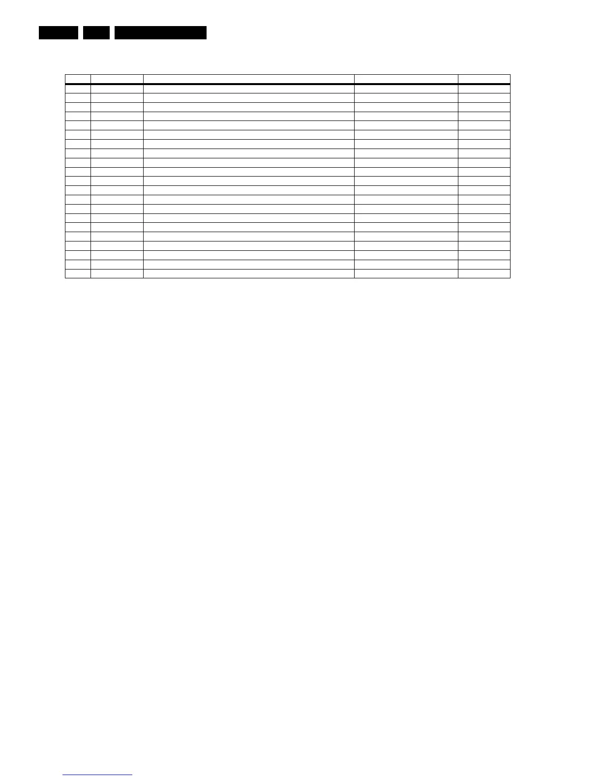
Table 5-3 Error codes overview
Note: Errors 7, 8, 13, 14 are not applicable.
5.6 The Blinking LED Procedure
Using this procedure, you can make the contents of the error
buffer visible via the front LED. This is especially useful when
there is no picture.
When the SDM is activated, the LED will blink the contents of
the error-buffer:
• When all the error-codes are displayed, the sequence
finishes with an 'on' LED blink of 1.5 seconds,
• The sequence starts again.
Example of error buffer: 12 9 6 0 0
After activating SDM, the following occurs:
• 1 long 'on' blink of 5 seconds to start the sequence,
• 12 short blinks followed by a pause of 1.5 seconds,
• 9 short blinks followed by a pause of 1.5 seconds,
• 6 short blinks followed by a pause of 1.5 seconds,
• 1 long 'on' blink of 1.5 seconds to finish the sequence,
• The sequence starts again at 12 short blinks.
5.7 Protections
If a fault situation is detected, an error code will be generated;
and, if necessary, the television set will go into protection
mode. Blinking of the red LED at a frequency of 3 Hz indicates
the protection mode. In some error cases, the microprocessor
does not put the set in protection mode. The error codes of the
error buffer and the blinking LED procedure can be read via the
Service Default Menu (SDM), or via ComPair.
To get a quick diagnosis the chassis has three service modes
implemented:
• The Customer Service Mode (CSM).
• The Service Default Mode (SDM).
• The Service Alignment Mode (SAM).
For a detailed description, see the "Customer Service Mode,
Service Default mode" and "Service Alignment Mode" sections.
Error Device Error description Check item Diagram
0 Not applicable No Error
1 Not applicable X-Ray / over-voltage protection (US only) 2411, 2412, 2413, 6404, 6411, 6412. A2
2 Not applicable High beam (BCI) protection 3404, 7405 A2
3 Not applicable Vertical guard protection 3466, 7451, 7452, 7453, 7454 A2
4 Tuner UA1316/A I2C error while communicating with 2nd tuner 1000, 5010 (PIP Module) F2
5 Not applicable +5v protection 7604, 7605 A5
6 I2C bus General I2C error 7200, 3207, 3214 A4
7 Not applicable - --
8 Not applicable - --
9 24C16 I2C error while communicating with the EEPROM 7601, 3604, 3605 A5
10 Tuner I2C error while communicating with the PLL tuner 1000, 5001 A3
11 TDA6107/A Black current loop instability protection 7330, 3351, CRT B1
12 SDA9488X I2C error while communicating with the PIP processor 7242 (PIP Module) F1
13 Not applicable - --
14 Not applicable - --
15 TDA9178T/N1 I2C error while communicating with LTI module 7610 H
16 TDA9887 I2C error while communicating with PIP_Demodulator 7201 F2
17 IBO Zapper No Communication possible with IBO Zapper module - K
18 IBO Zapper General error from IBO Zapper module - K
19 TDA1200 I2C error while communicating with SSD stereo sound decoder 7200 A4
20 TDA1200 I2C error while communicating with video cosmic in Hercules IC 7200 A4